
The Bloor Viaduct stands as one of Toronto’s most recognizable structures. Stretching more than 300 meters across the Don River Valley, it links the east and west sides of the city along Bloor Street. Construction began in 1914 and finished in 1918, costing approximately $3.5 million dollars. Engineers Horace Roupe and Gustav Hahn designed the bridge, and hundreds of workers — engineers, ironworkers, and laborers — carried out the work under the management of the City of Toronto.
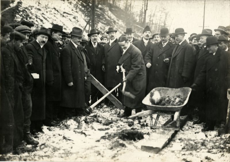
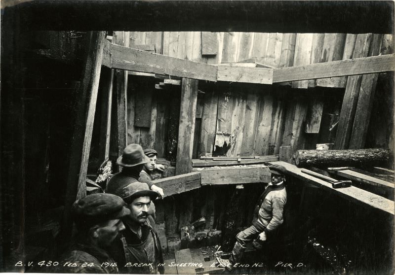
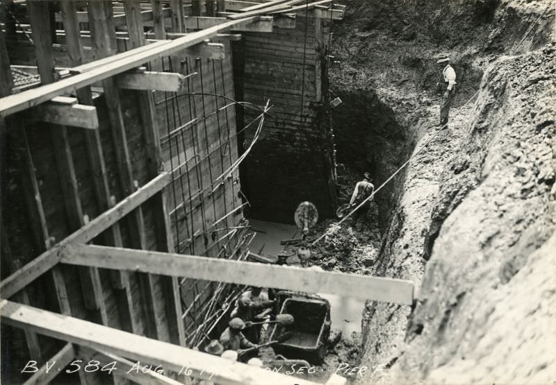
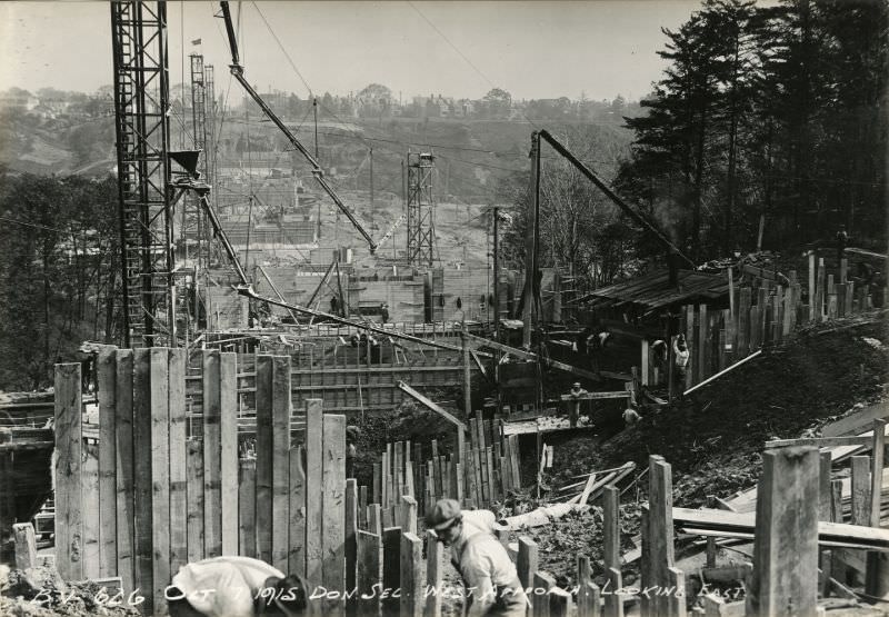
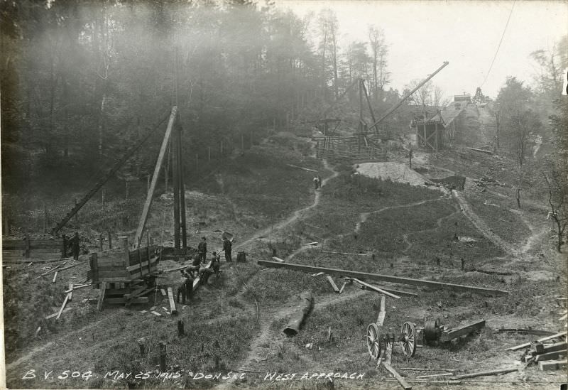
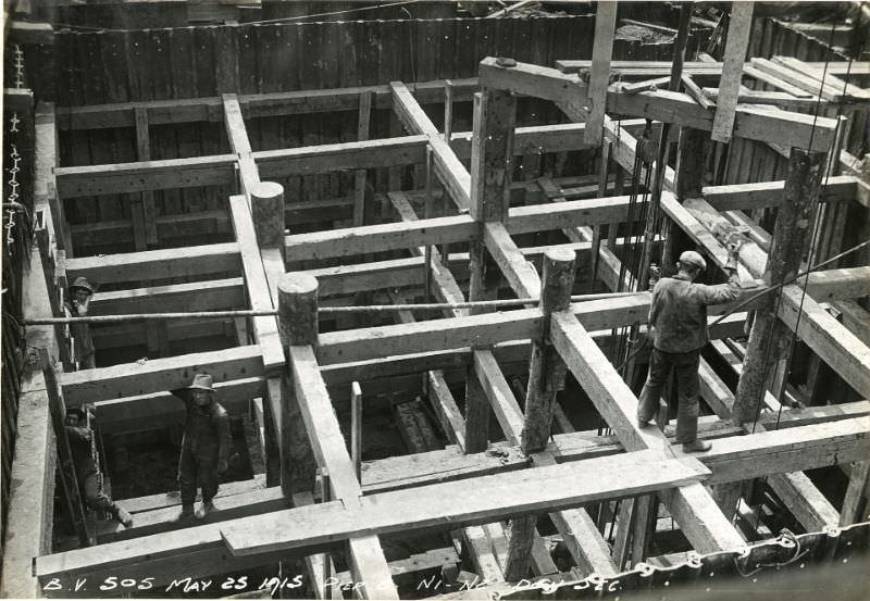
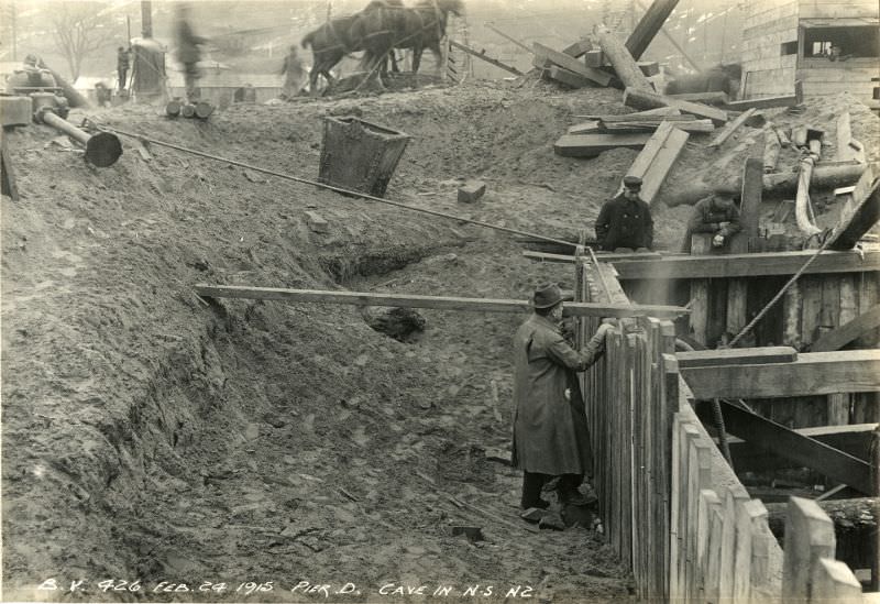
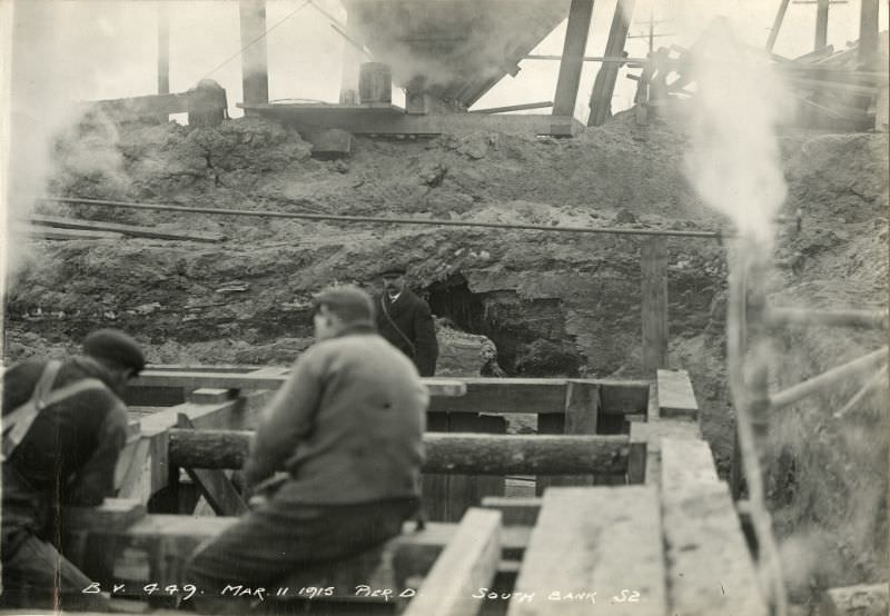
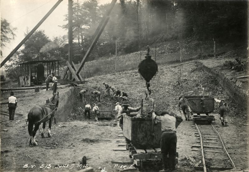
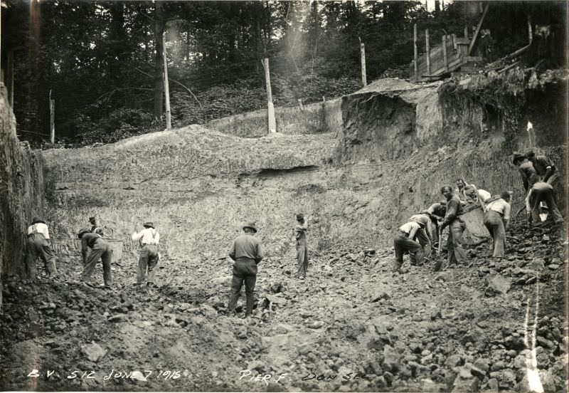
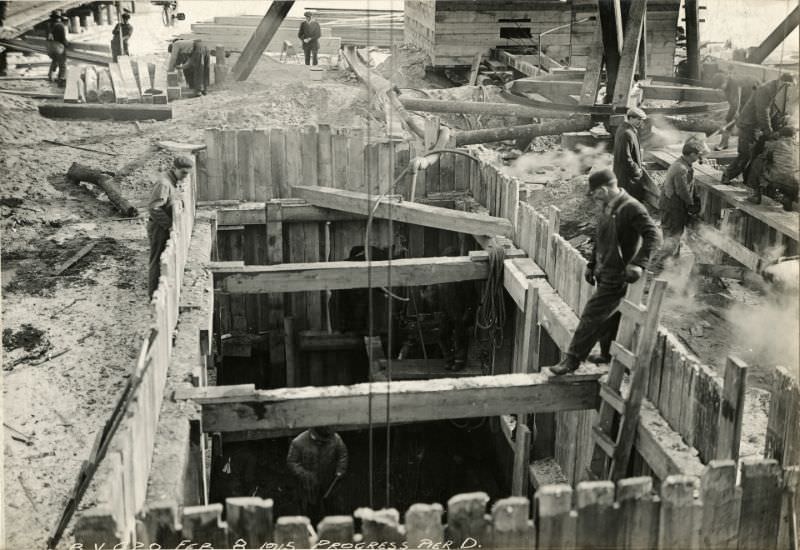
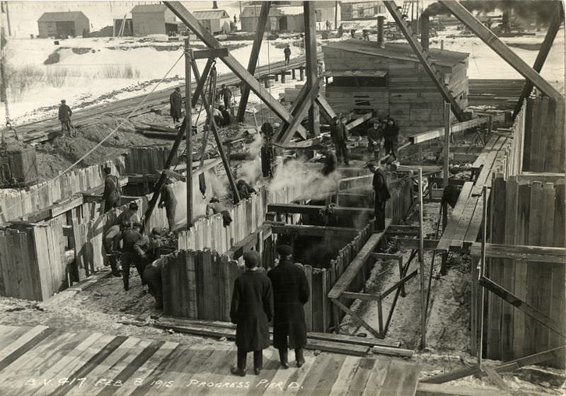
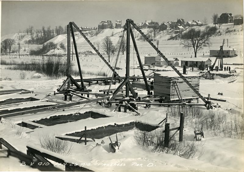
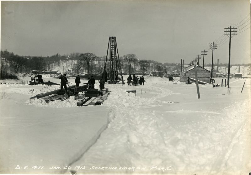
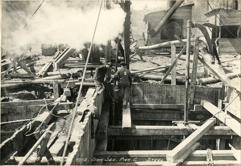
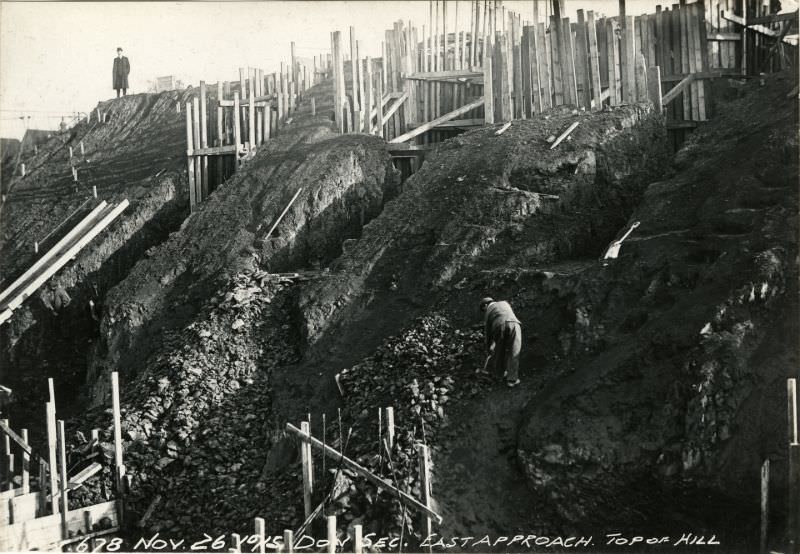
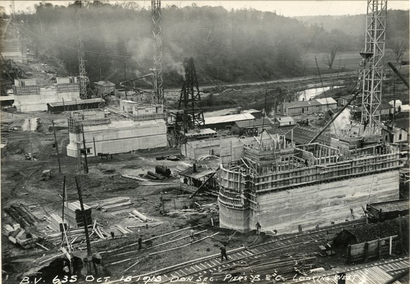
Work on the bridge’s piers began at ground level, deep in the Don River Valley. Steel sheet piling was driven into the earth to hold back soil and water while crews excavated the foundations. Early construction photos show the raw conditions workers faced — open cuts in the ground, exposed subsoil, and the ever-present threat of flooding from the Don River below.
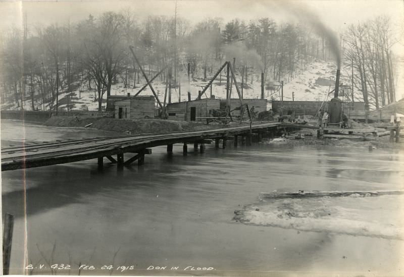
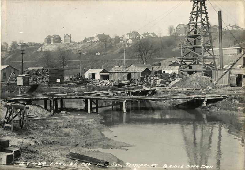
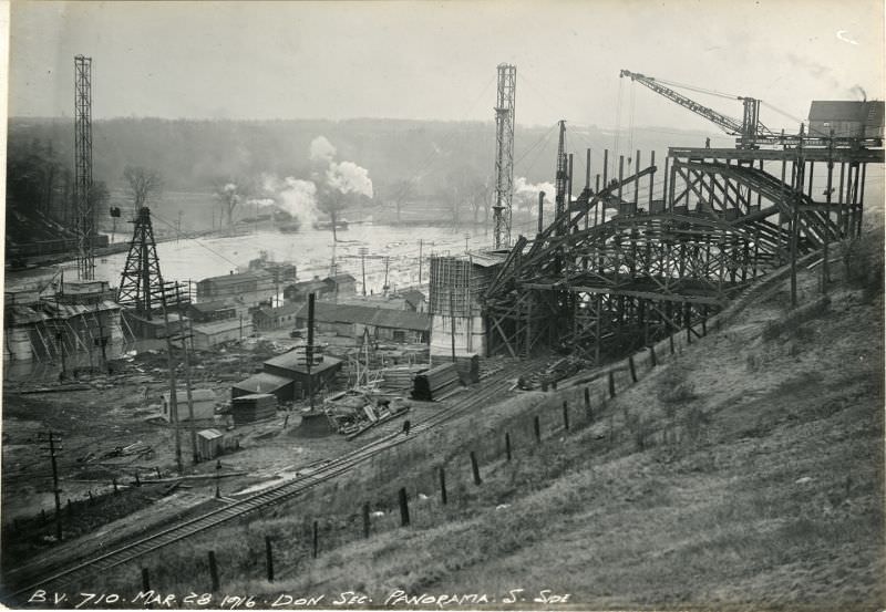
The Don River posed a real challenge throughout construction. When the river flooded, worksites were submerged and schedules were disrupted. A temporary bridge was built over the Don to keep the project moving, allowing materials and workers to cross the valley without interruption.
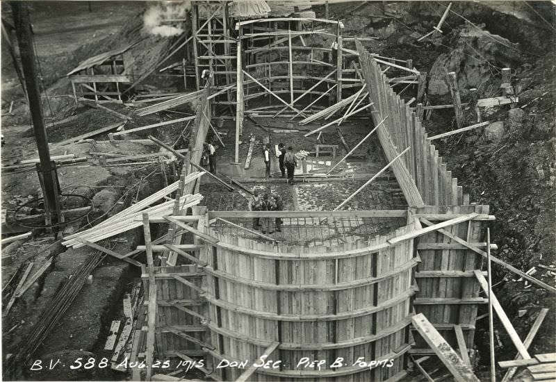
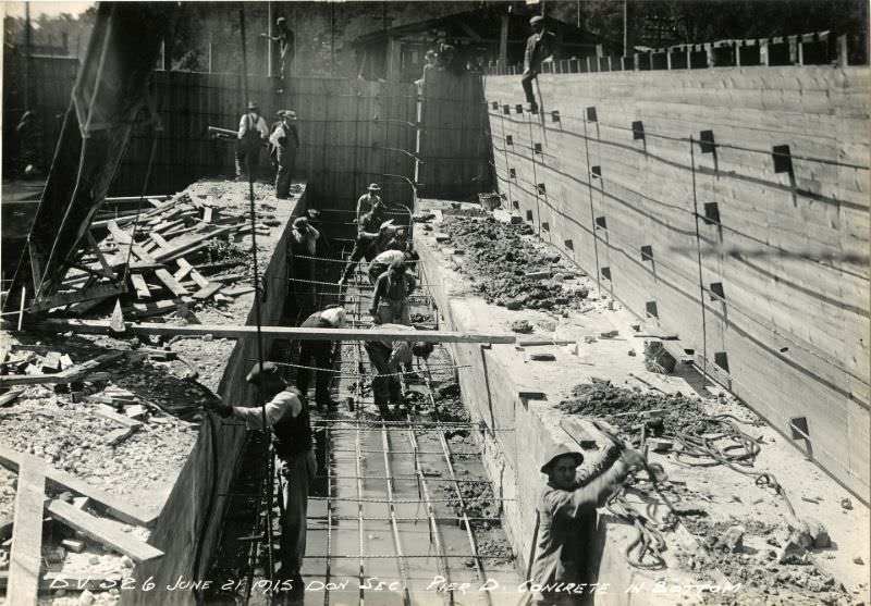
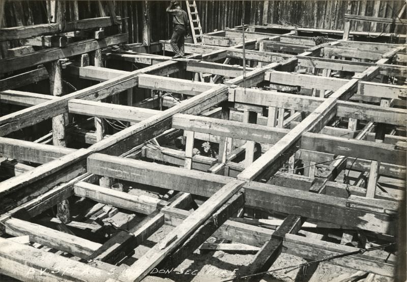
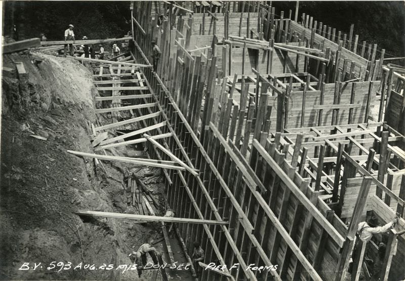
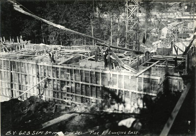
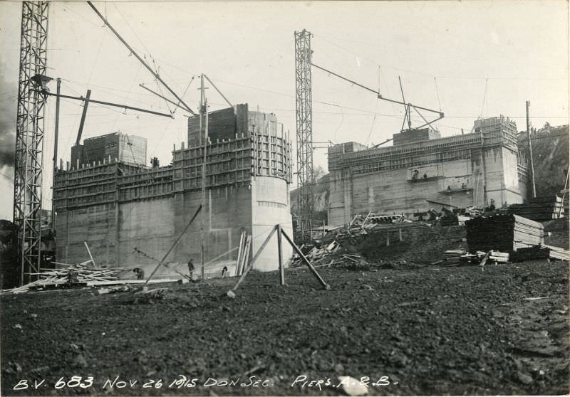
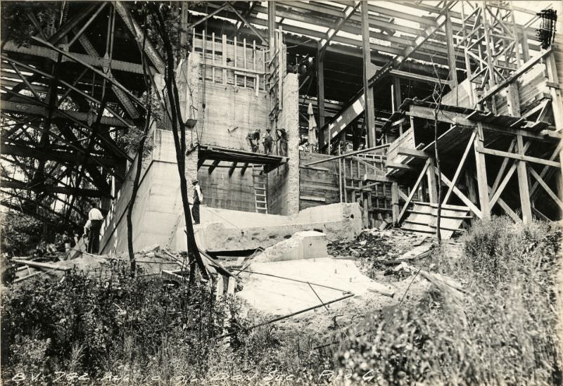
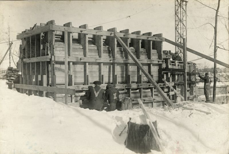
Concrete forms were constructed around each pier location before the concrete was poured. These wooden forms gave the wet concrete its shape while it cured. Photos from Piers B, D, E, and F show the forms at various stages — some empty and freshly assembled, others already receiving poured concrete at the bottom.
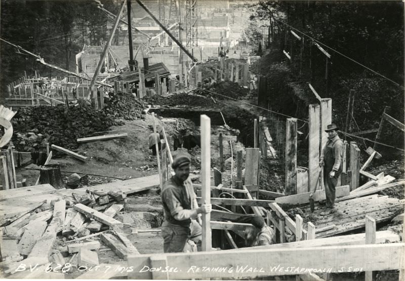
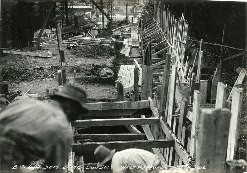
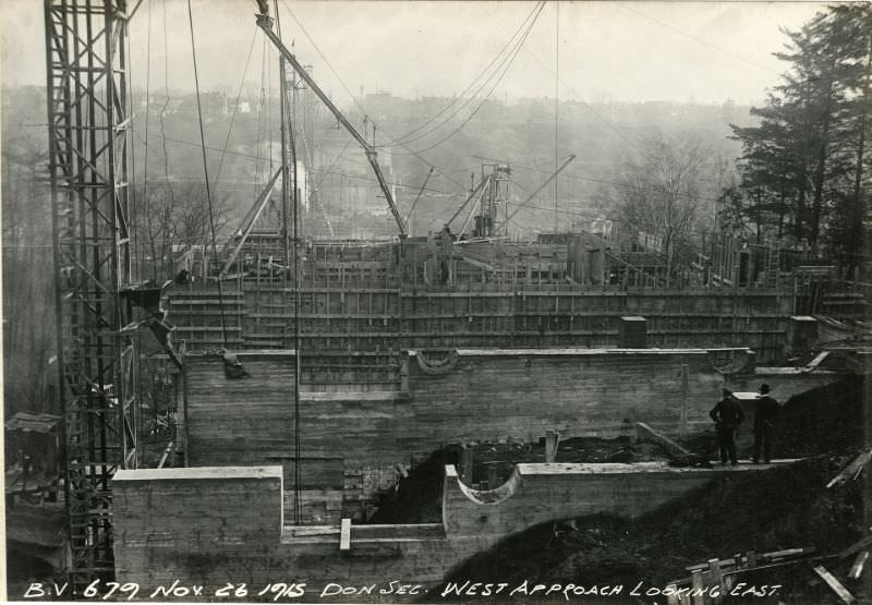
While pier foundations were being set, work was also underway on the approach sections — the sections of the bridge that lead into the main span from either side. The west approach required a retaining wall along the south side to stabilize the sloped terrain of the valley’s edge.
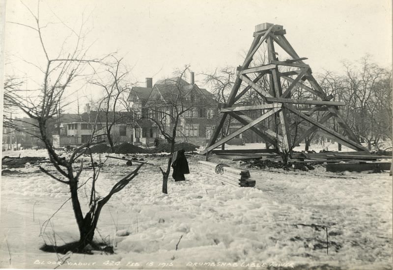
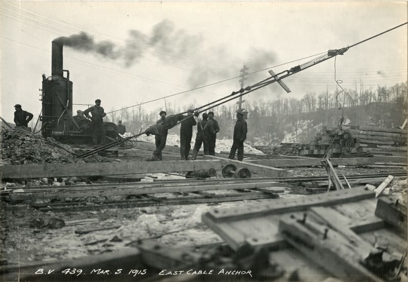
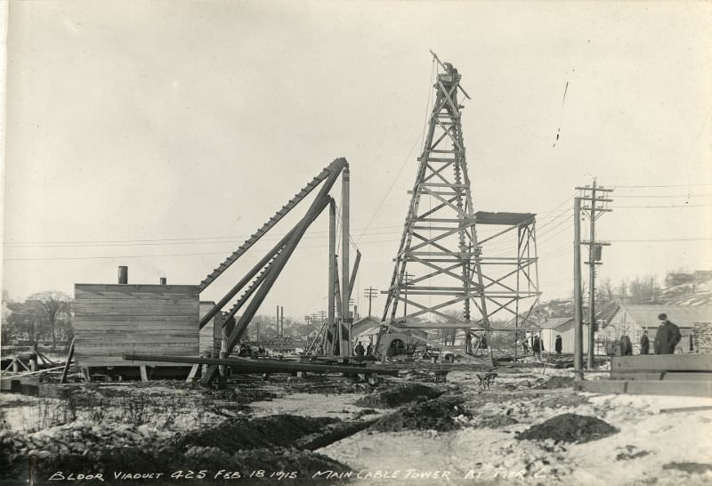
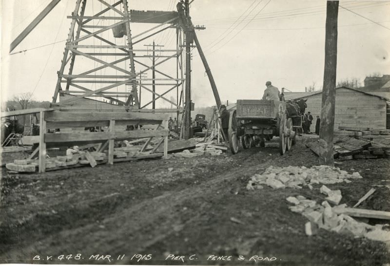
To move heavy steel and materials across the valley during construction, crews erected cable towers at key points along the site. The Drumsnab Cable Tower and the main cable tower at Pier C are documented in several photographs. These towers acted as aerial cranes, suspending cables that could carry loads across sections where ground access was difficult.
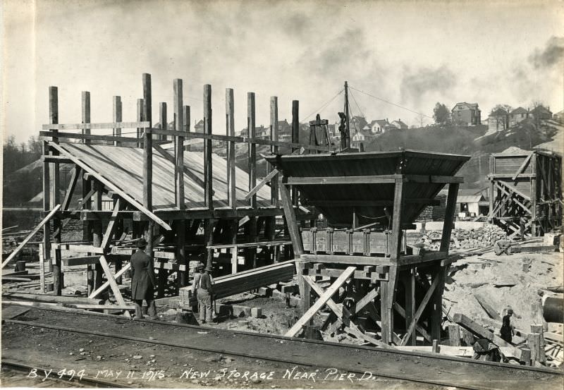
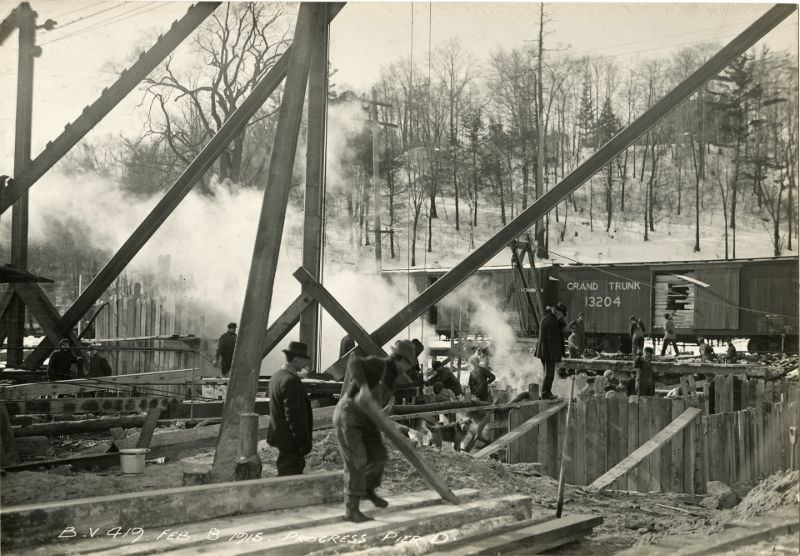
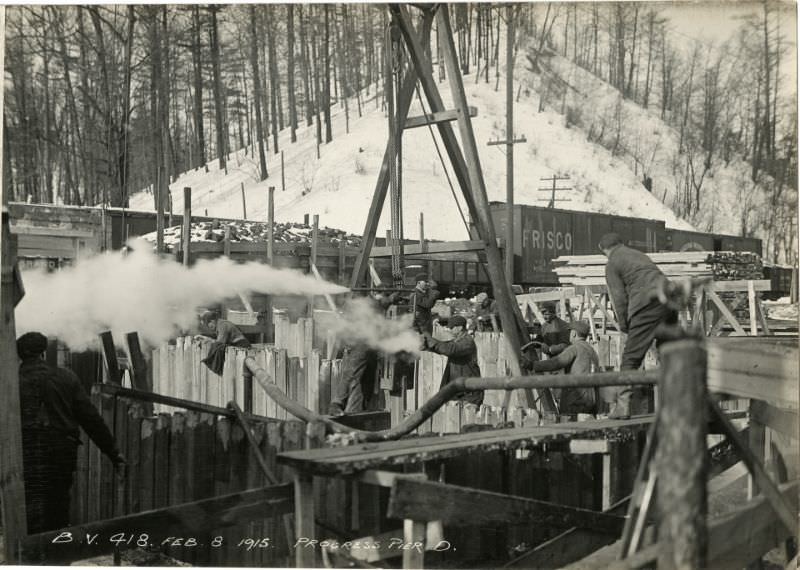
Storage areas near the piers held the steel beams and hardware needed for assembly. All of the steel used in the bridge’s truss arches was manufactured at the Canadian Bridge Company in Walkerville, Ontario, then shipped to the Toronto site. Tracking progress at Pier D was clearly a priority — a full sequence of photographs documents its construction from the earliest excavation through to the finished pier.
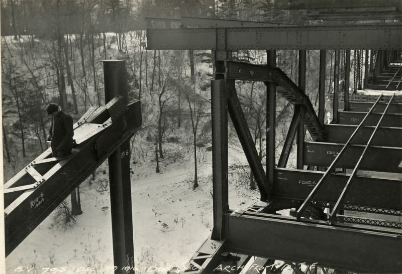
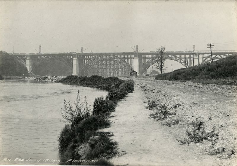
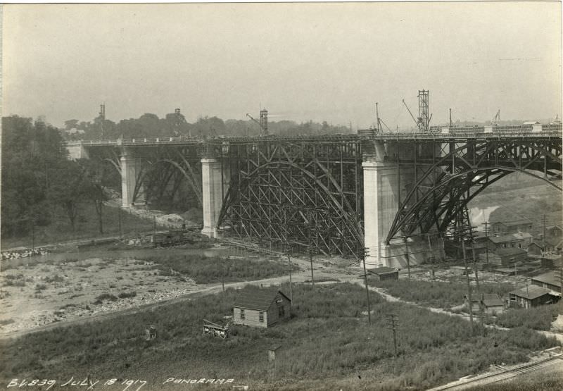
With the piers rising from the valley floor, work shifted to the steel superstructure. The Bloor Viaduct is made up of two parallel bridges, each with its own independent truss arch system. The arches are built from steel beams arranged in triangular patterns, which distribute the bridge’s load efficiently across the span. Workers used the cantilever method to erect the steel — building outward from both ends simultaneously until the two halves connected in the middle.
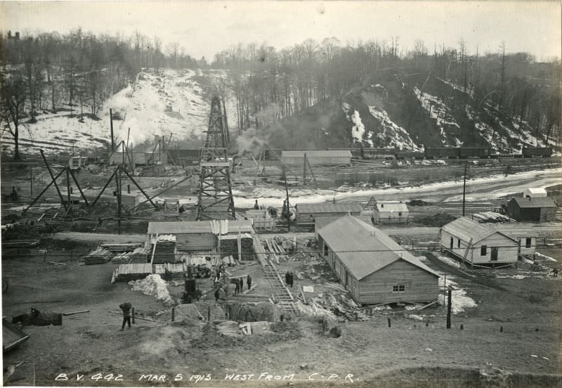
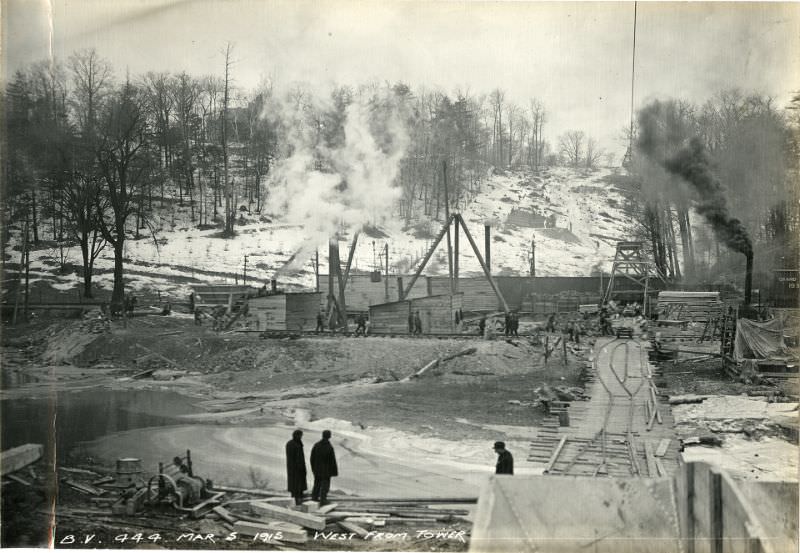
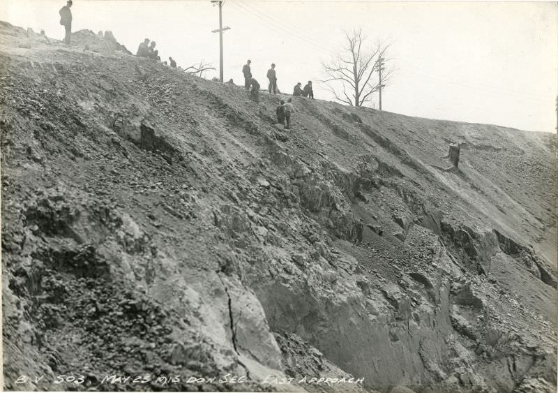
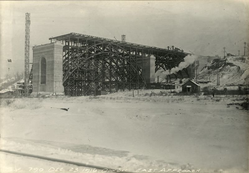
Panoramic views taken from the tower and from the CPR line to the west capture the full scale of the project as it progressed. The east approach, photographed from the top of the hill, shows the graded roadbed taking shape as it descends toward the valley.
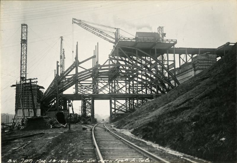
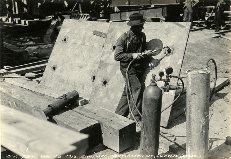
The truss arches between piers were among the most technically demanding parts of the build. Photos labeled “Arch From D to E” and “Arch From A to B” show the steel framework mid-assembly, suspended above the valley. Oxy-acetylene cutting equipment was used on-site to trim and fit steel sections, a method documented in one of the construction photographs.
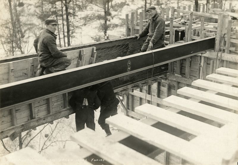
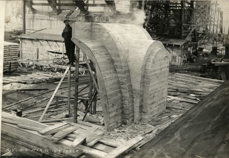
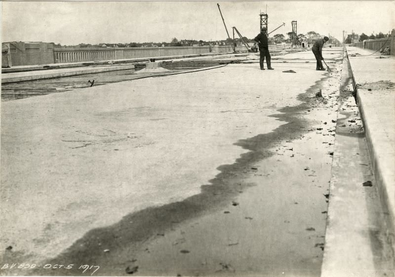
As the structural steel neared completion, crews turned to forming the concrete deck. Wooden forms — apron walls, central deck forms, and outer deck frames — were installed between and over the steel arches. These forms supported wet concrete until it hardened into the flat road surface that would carry traffic above the valley.
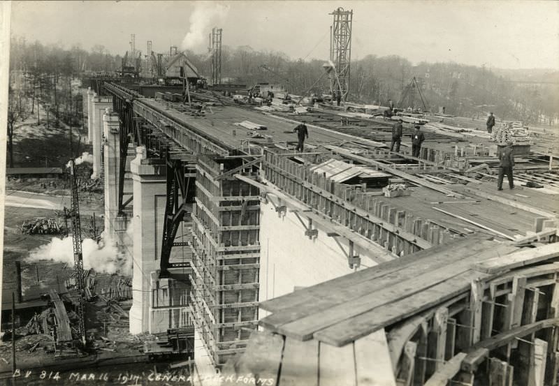
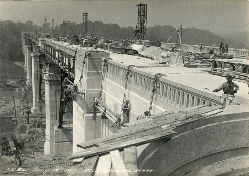
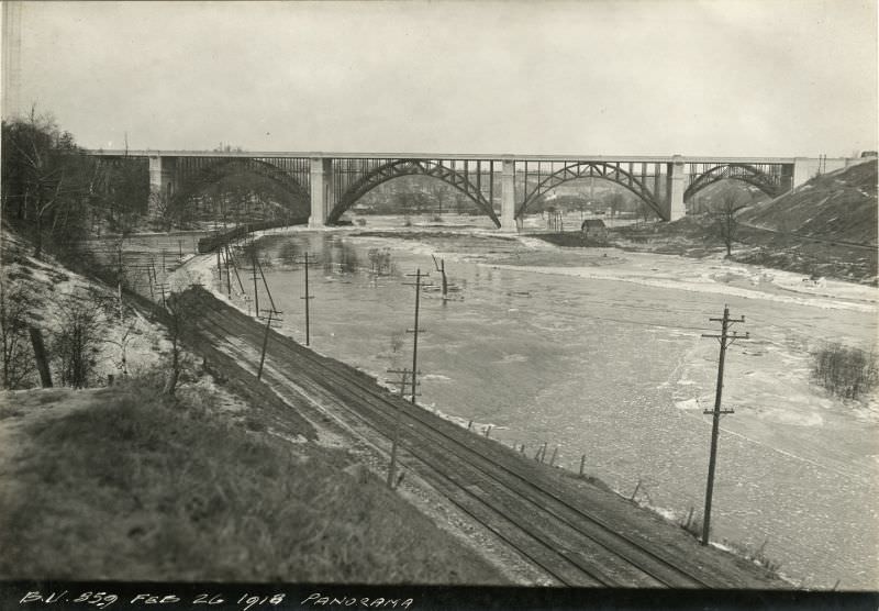
A general view of the 281-foot main span, along with panoramic shots looking south and east along the upper deck, shows the bridge in its near-complete state. The scale of the finished structure is striking when compared to the raw excavations photographed just four years earlier.
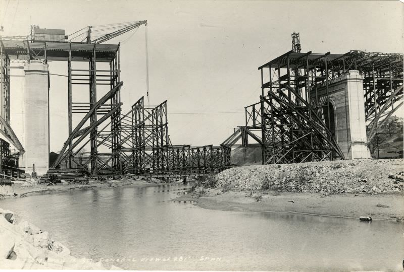
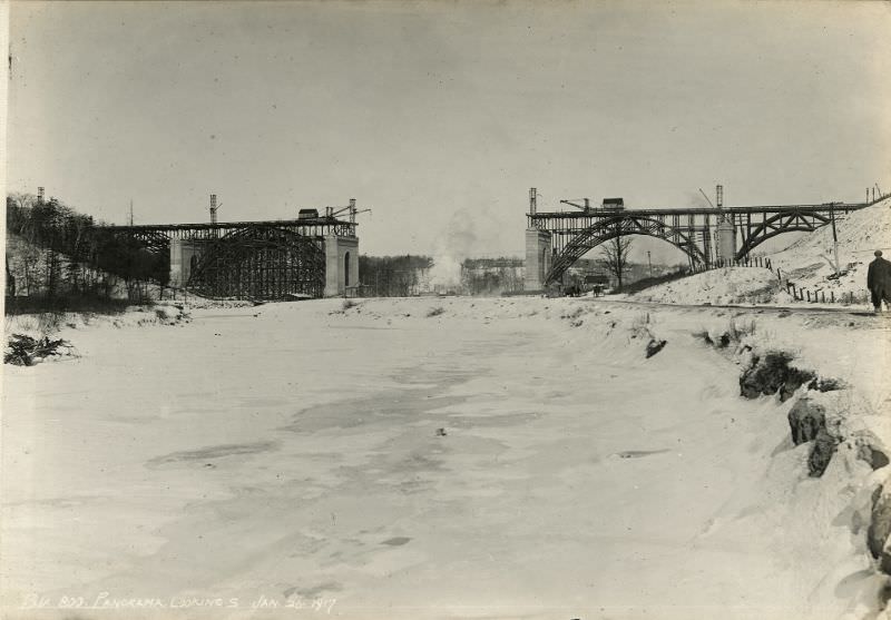
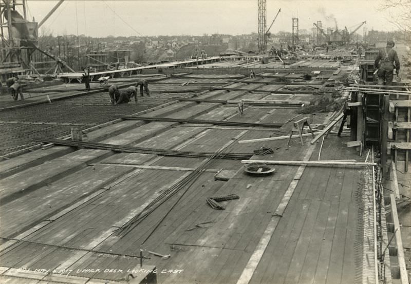
The final panoramic photographs of the Bloor Street Viaduct document the bridge as construction wrapped up and the site was cleared. These images capture a structure that had taken four years, hundreds of workers, and millions of dollars to complete — rising fully formed across the Don River Valley.



Does anyone else see empty statue niches at the top of every concrete support? It always seems to me that there are eight statues missing…