
Hey There! Before You Go. 😧
Get the best vintage content straight into your inbox!

Don't worry, we don't spam

NASA's massive Wind Tunnels that were used to test Aircrafts, 1925-1990

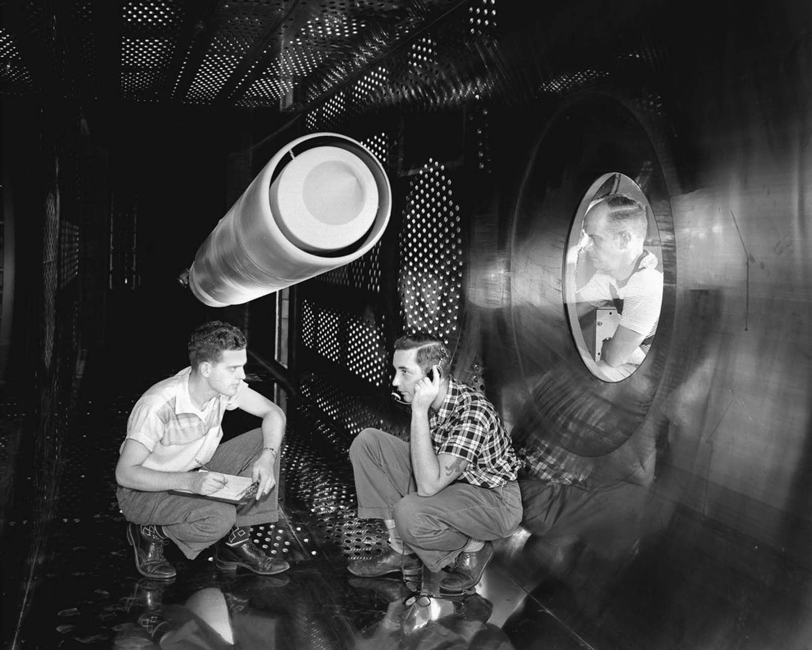
Before any aircraft or spacecraft is cleared to fly, it has to survive a gauntlet of tests. For NASA and its predecessor, the National Advisory Committee for Aeronautics (NACA), that process ran through an extensive network of wind tunnels — 42 major facilities in total. These weren’t simple machines. Some were small enough to test a model the size of your hand. Others were large enough to swallow a full-size airplane whole. Together, they formed the backbone of American aerospace research for most of the 20th century.

The core idea behind a wind tunnel is straightforward. Rather than sending an object flying through still air, engineers reverse the situation: they keep the object stationary and push the air past it. The result is the same — the aerodynamic forces acting on the object are real and measurable — but a stationary observer can actually study what’s happening. Smoke or dye is often added to the airflow to make it visible, turning invisible forces into something engineers can watch and record. Large fans pull the air through the tunnel at controlled speeds, and the data collected guides every design decision that follows.

Wind tunnels first appeared at the end of the 19th century, born out of the race to build the first successful heavier-than-air flying machine. By 1916, the US Navy had built one of the largest in the world at the Washington Navy Yard, with an inlet nearly 11 feet in diameter and a 500-horsepower electric motor driving its paddle-type fan blades. That tunnel set a standard for the engineering ambition that would define the field for decades.

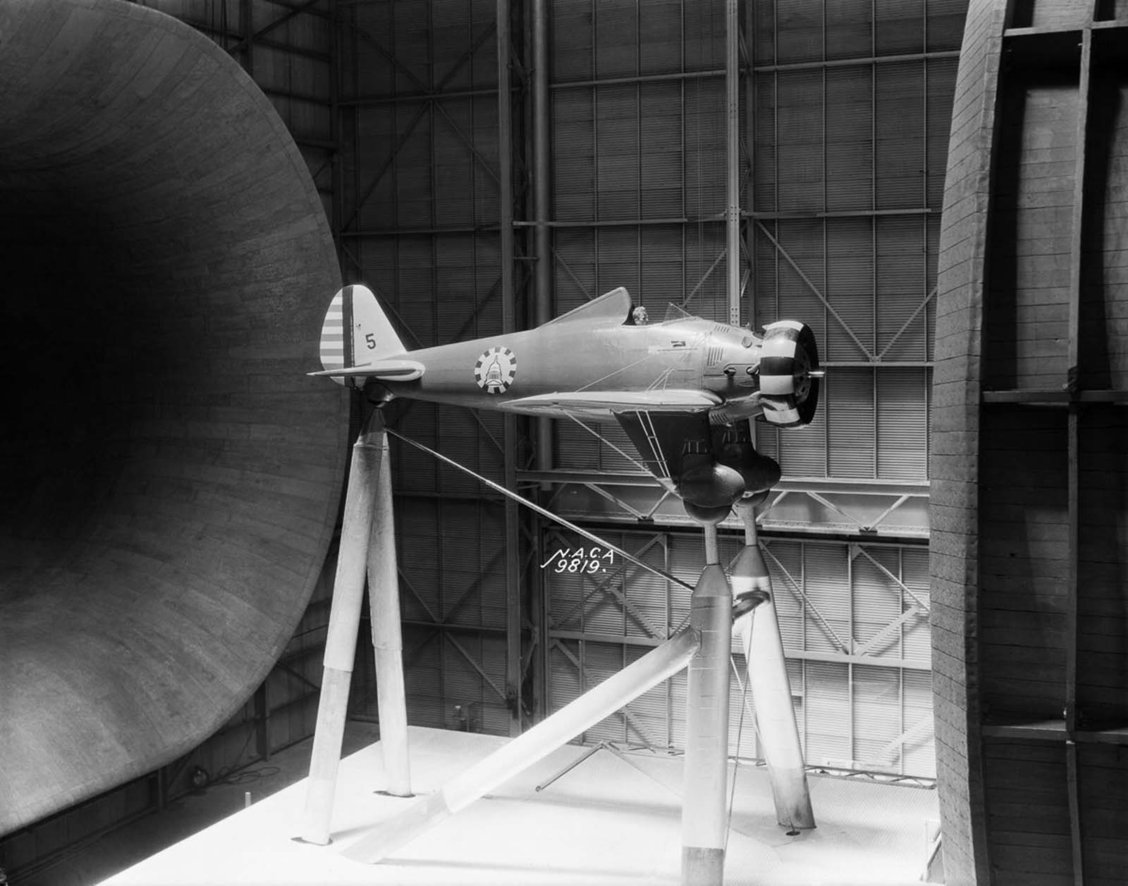
One of the most important facilities ever built was the 30-by-60-foot Full Scale Tunnel at Langley Research Center in Virginia, completed in 1931. Powered by two electric motors rated at a combined 8,000 horsepower, it used a closed-loop, double-return layout and could accommodate actual full-size aircraft — not just scale models. One of its earliest subjects was a Boeing P-26A fighter, a cutting-edge military aircraft of its era.

A Boeing P-26A fighter mounted in the 30 x 60 Full Scale Tunnel.

Nicknamed the

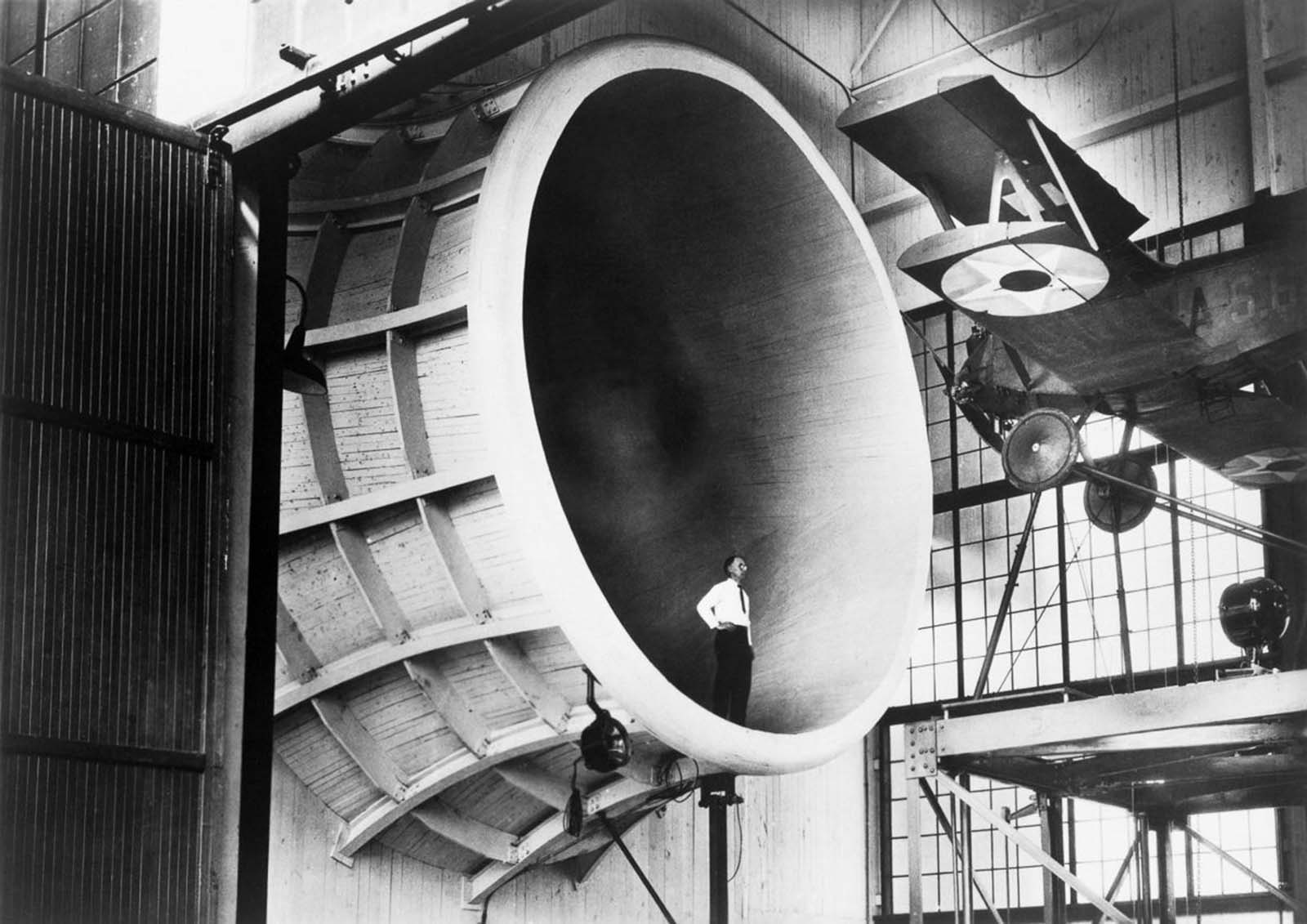
Even before the Full Scale Tunnel opened, Langley’s Propeller Research Tunnel was already producing results. In 1927, researchers used it to test the first full-scale airplane to ever pass through a wind tunnel of that type — a Sperry M-1 Messenger, a small biplane used by the Army.

A Langley researcher observes a Sperry M-1 Messenger, the first full-scale airplane tested in the Propeller Research Tunnel, 1927.

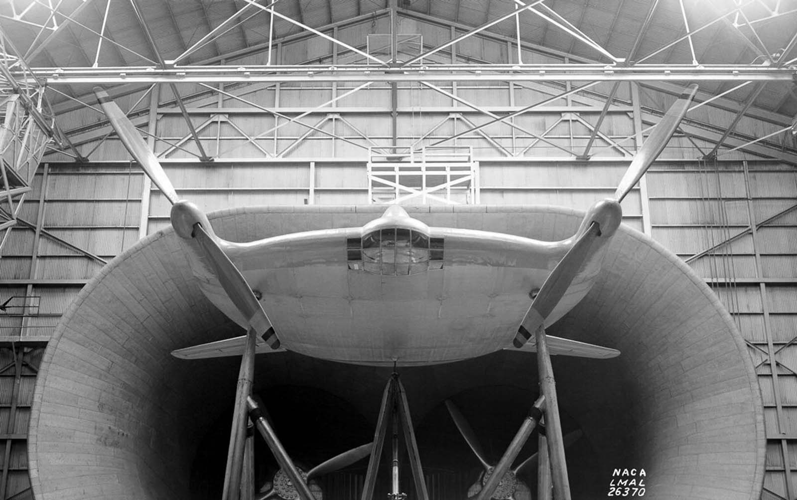
Through the 1930s and into World War II, the Full Scale Tunnel at Langley became a proving ground for experimental aircraft designs. One of the stranger-looking subjects was the Vought-Sikorsky V-173, a prototype with an unusually flat, disc-like fuselage that earned it the nickname “the Flying Pancake.” Its unconventional shape required careful aerodynamic study before any flight tests could begin.

A prototype Vought-Sikorsky V-173 airplane mounted in the Full Scale Wind Tunnel, 1941.

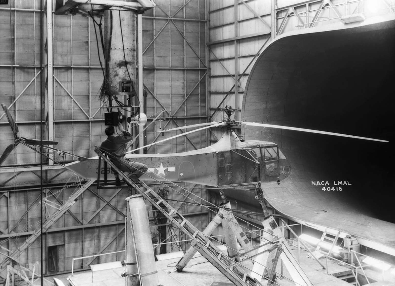
The war years accelerated tunnel development at a rapid pace. The United States built eight new wind tunnels during World War II alone. One of the most significant was constructed at Wright Field in Dayton, Ohio — a tunnel that began at 45 feet in diameter and narrowed to 20 feet, powered by a 40,000-horsepower electric motor driving two 40-foot fans. It could push aircraft models to 400 miles per hour. A separate vertical tunnel at Wright Field, where airflow moved upward rather than horizontally, was used to test the concept designs behind the first primitive helicopters.

A Sikorsky YR-4B/HNS-1 helicopter, the first mass-produced chopper, in the 30 x 60 Full Scale Tunnel, 1944.

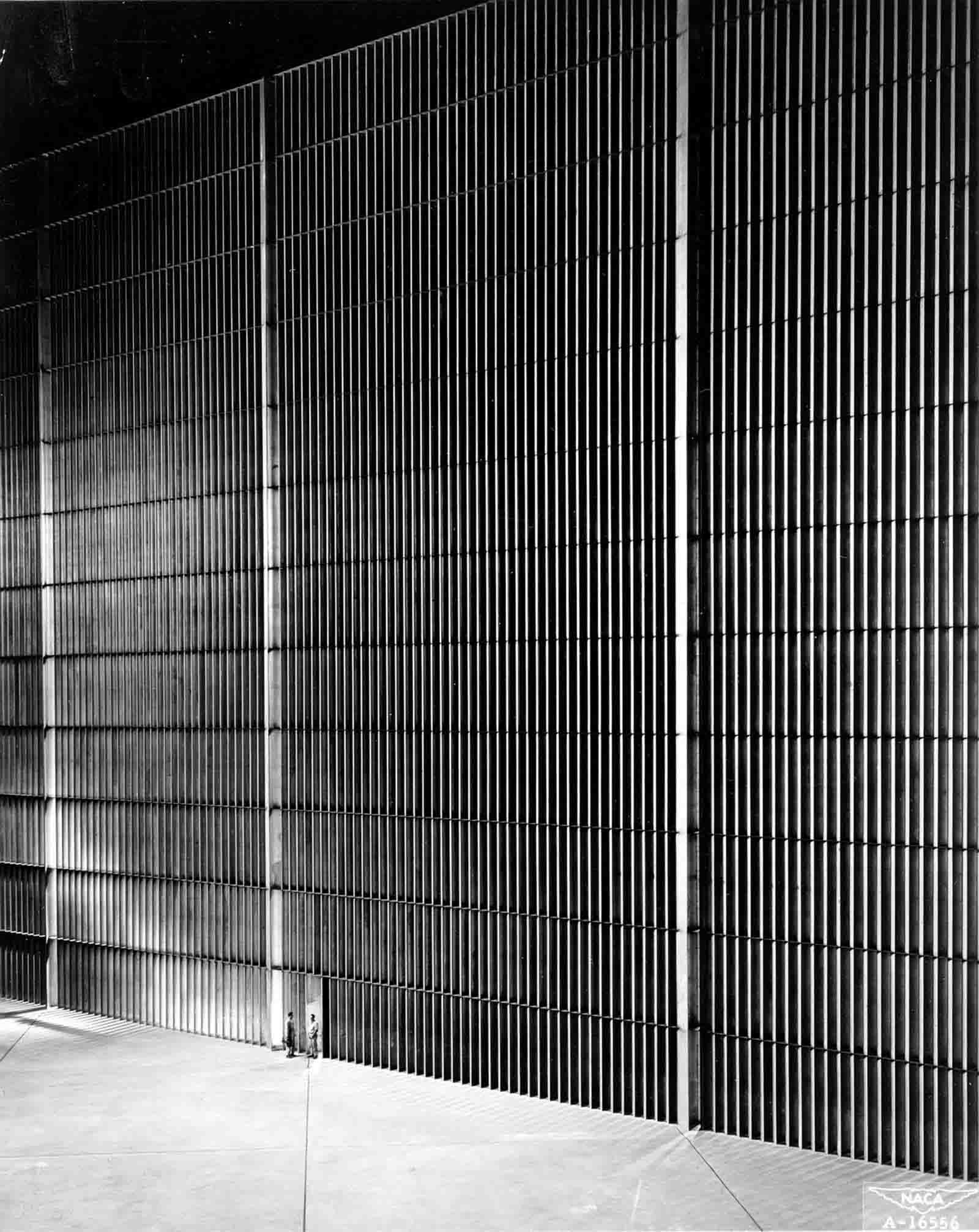
The largest wind tunnel built during that wartime expansion was located at Moffett Field near Sunnyvale, California, at what was then the Ames Aeronautical Laboratory. Designed to test full-size aircraft at speeds below 250 mph, the 40-by-80-foot tunnel was the largest in the world at the time of its completion. Its scale required enormous engineering infrastructure, including 10-story banks of turning vanes at its corners to redirect airflow through the closed-loop system.

The 40 x 80-foot wind tunnel at Ames Aeronautical Laboratory, Moffett Field, California.

At the time of its construction it was the largest wind tunnel in the world, 1947.

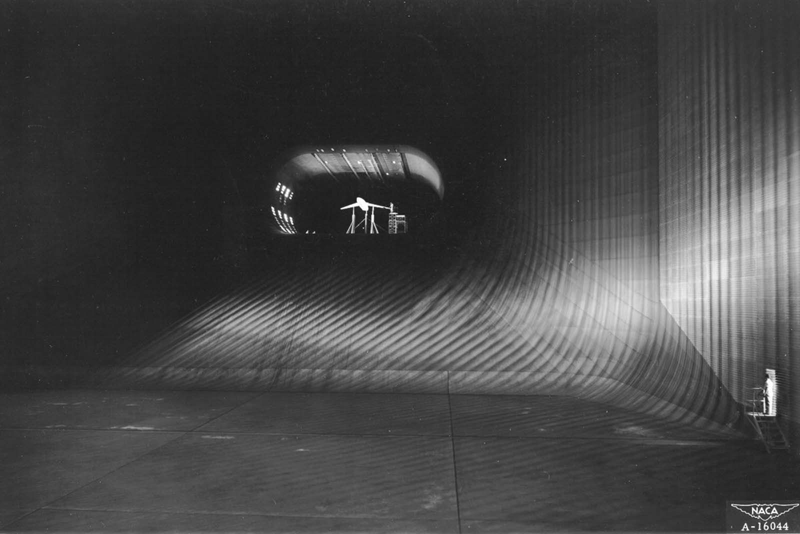
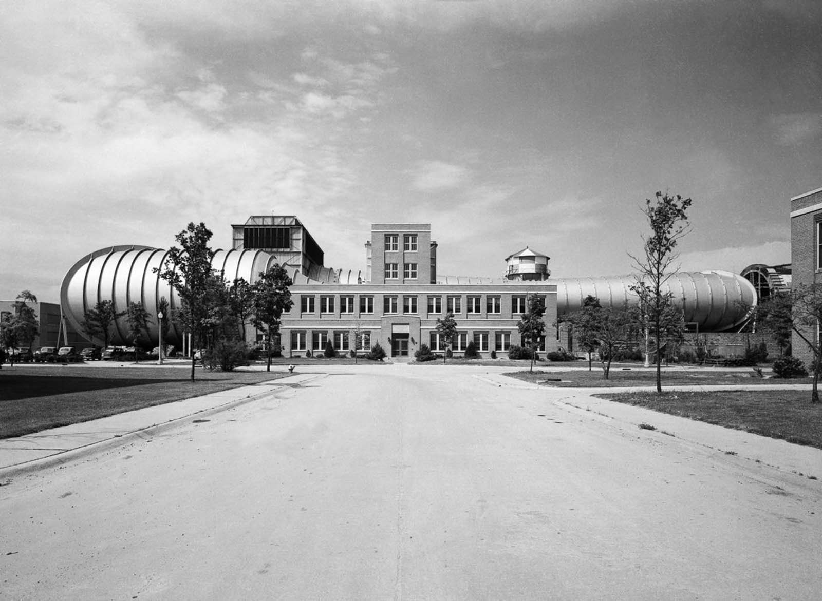
As jet aviation matured in the postwar years, engineers needed tunnels that could simulate far greater speeds. High-speed tunnels capable of reaching subsonic, transonic, supersonic, and eventually hypersonic velocities — five times the speed of sound — were developed at facilities across the country. Langley’s 16-Foot High Speed Tunnel, operational by the late 1940s, was one of the key tools in this new era of research.

The 16-foot High Speed Tunnel at Langley Research Center, 1949.

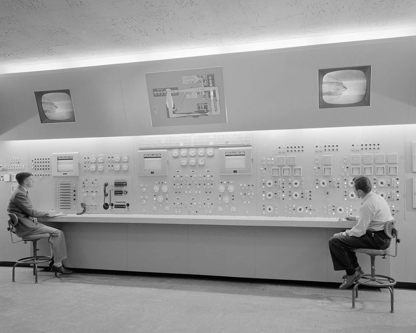
The complexity of operating these tunnels matched their physical scale. Facilities like the Lewis Unitary Plan Wind Tunnel required dedicated control rooms staffed by engineers monitoring multiple instrument panels simultaneously. Every test run was a coordinated effort between technicians, researchers, and the machinery itself.

One of three control panels in the control room of the Lewis Unitary Plan Wind Tunnel, 1955.

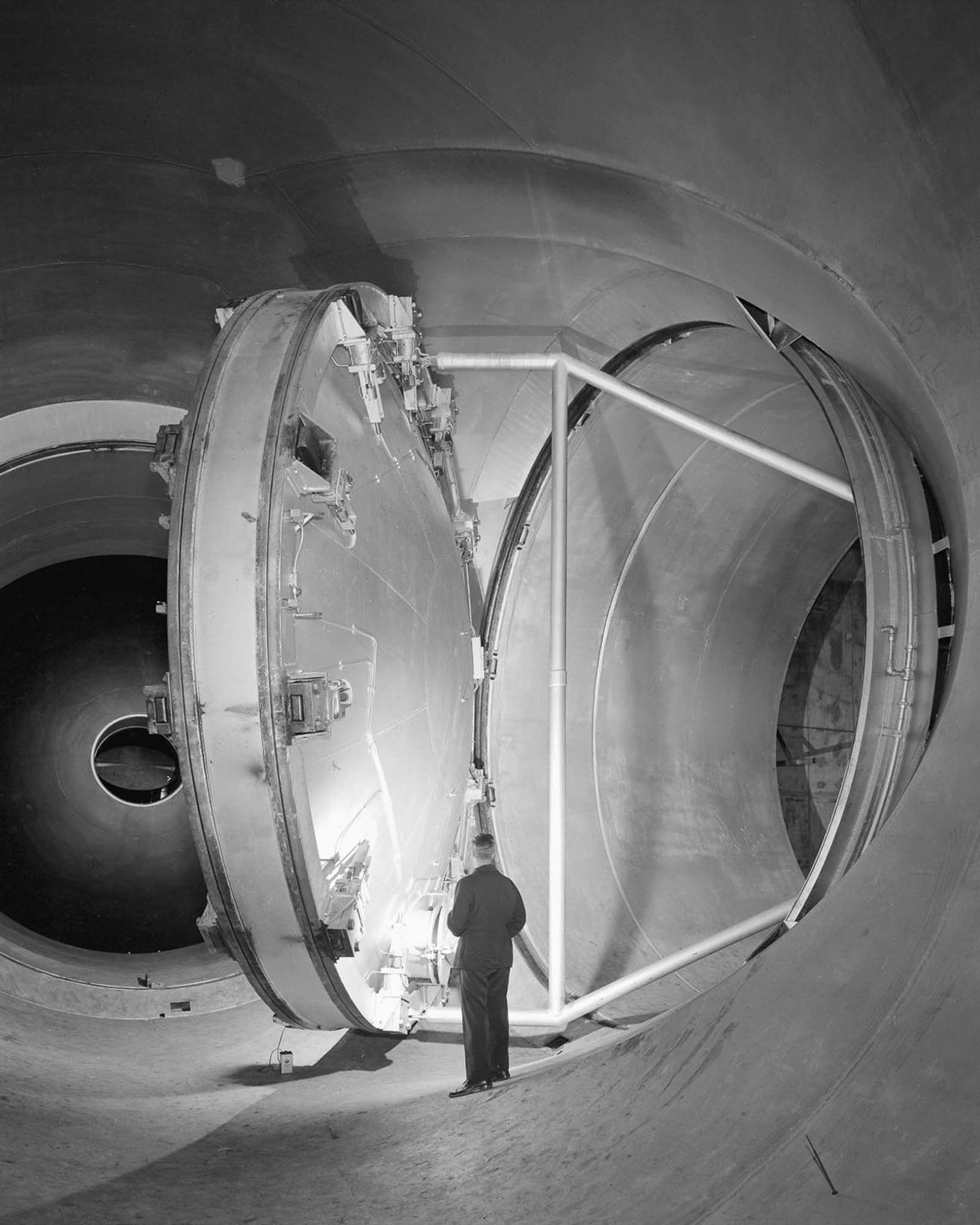
Supersonic tunnels introduced a new set of mechanical challenges. Managing airflow at those speeds required precisely engineered components — including massive swinging valves that controlled pressure and flow rates within the test sections.

A 24-foot swinging valve in the 10 x 10-foot Supersonic Wind Tunnel, 1956.

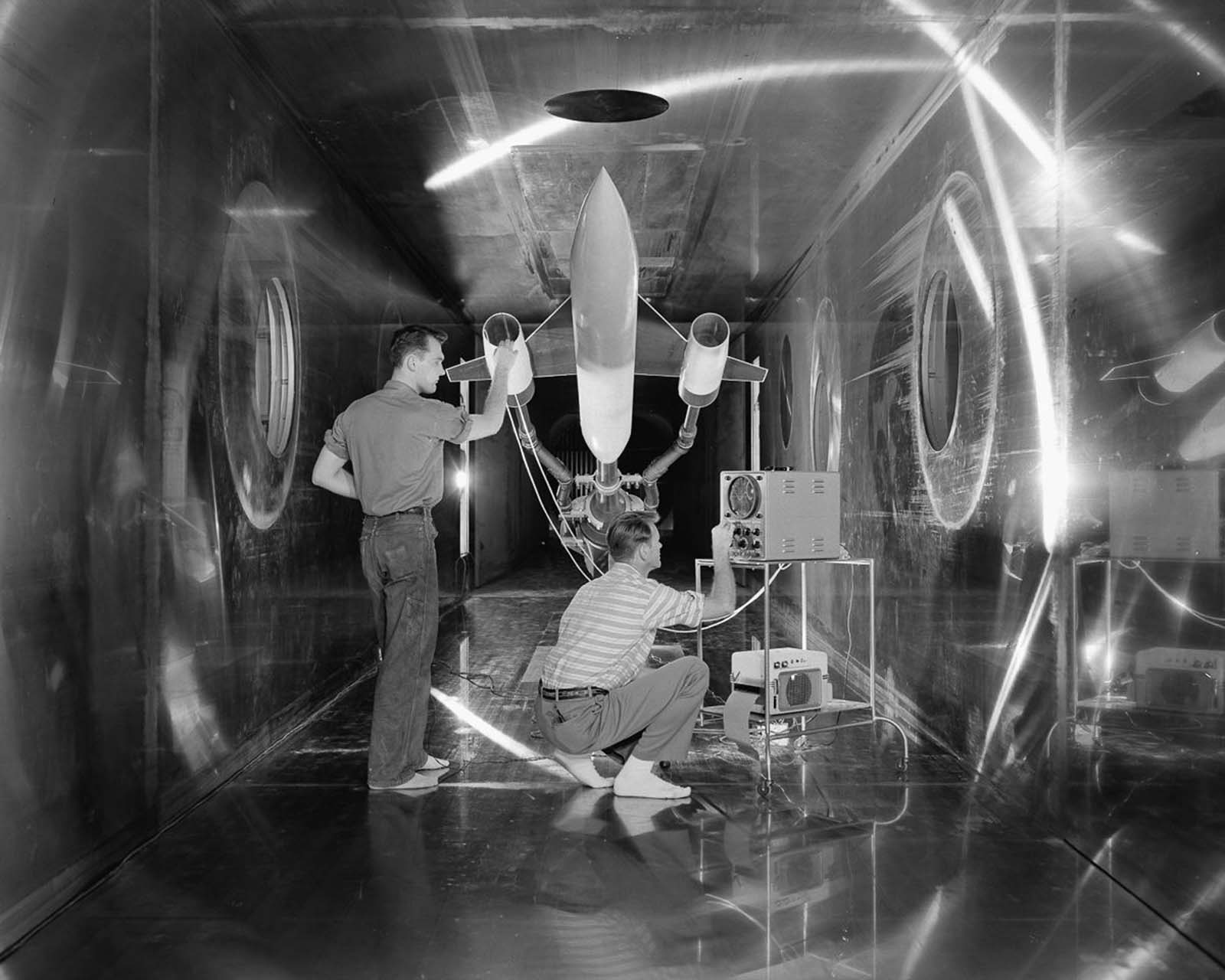
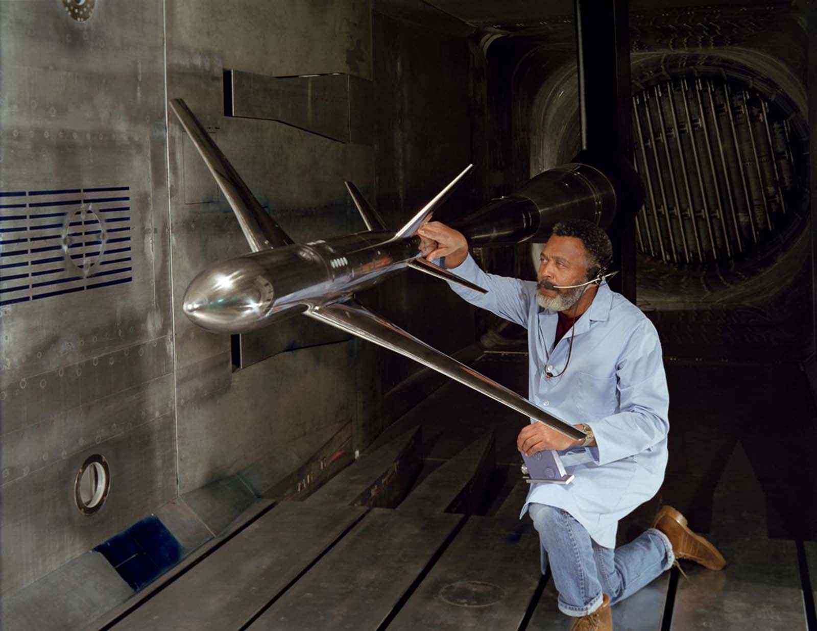
Inside the supersonic test sections, engineers worked with scale models of aircraft and engine components, fine-tuning shapes to reduce drag and improve stability at speeds the human eye could barely track. Nozzle designs were among the most critical elements tested, directly affecting engine efficiency and aircraft performance.

An ACN Nozzle model in the 8 x 6-foot Supersonic Wind Tunnel Test-Section, 1957.
Engineers make a check of a model of a supersonic aircraft before a test run in the 10 x 10-foot Supersonic Wind Tunnel test section, 1957.

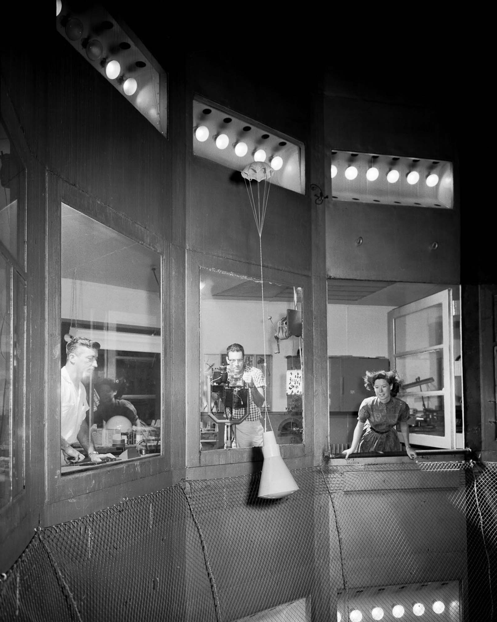
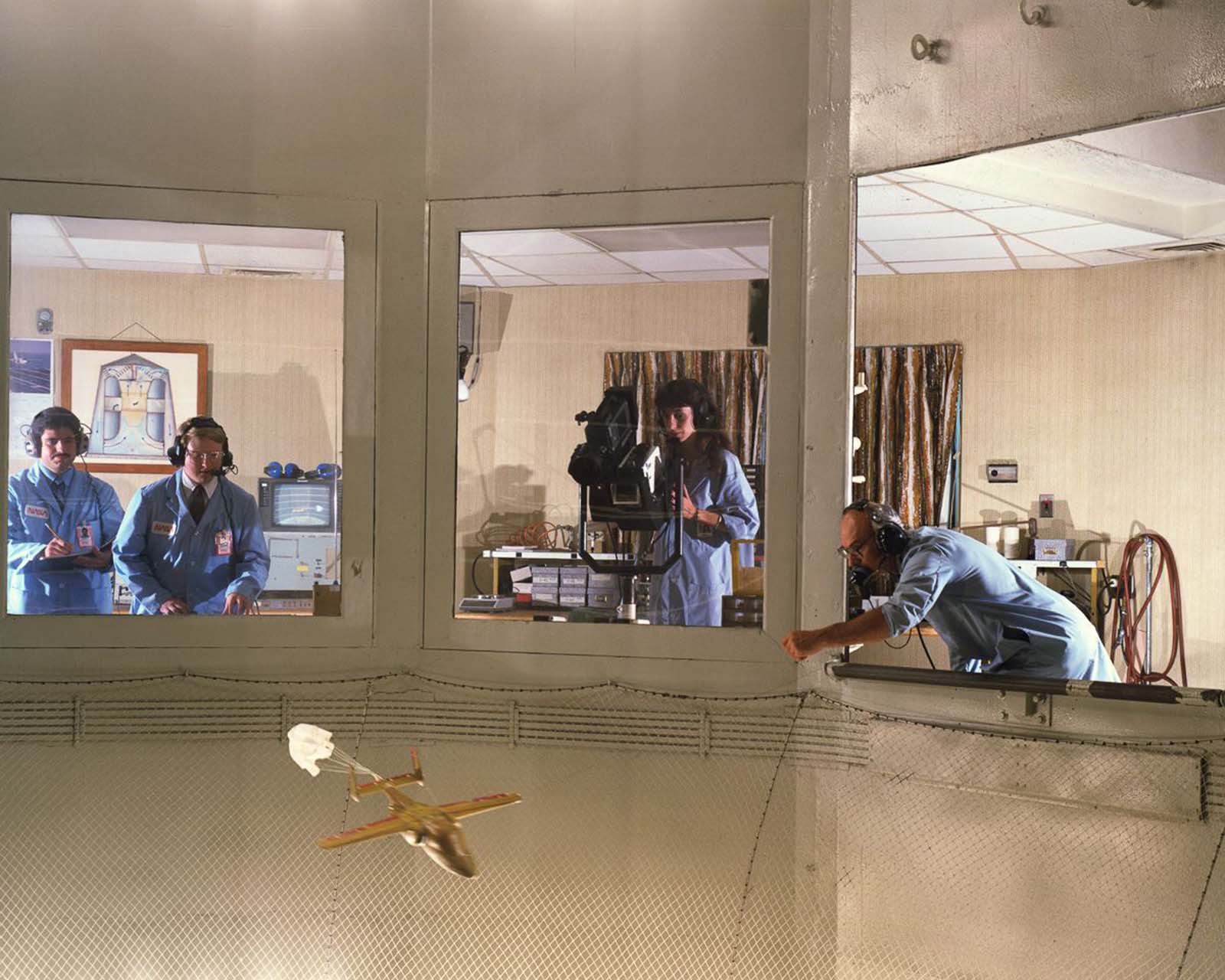
By the late 1950s, the space race had added an entirely new category of test subject. NASA’s early capsule designs — including the Mercury program — required testing in Spin Tunnels, which studied how a vehicle behaved in a rotating, uncontrolled descent. Understanding spin dynamics was critical for recovery systems and astronaut safety.

A Mercury Capsule model in the Spin Tunnel, 1959.

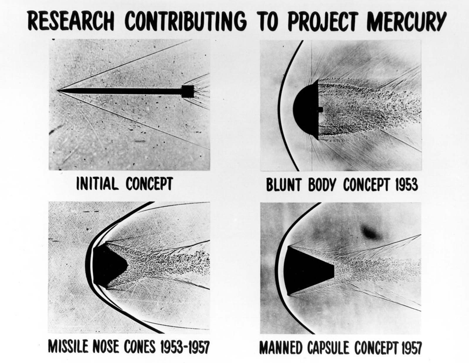
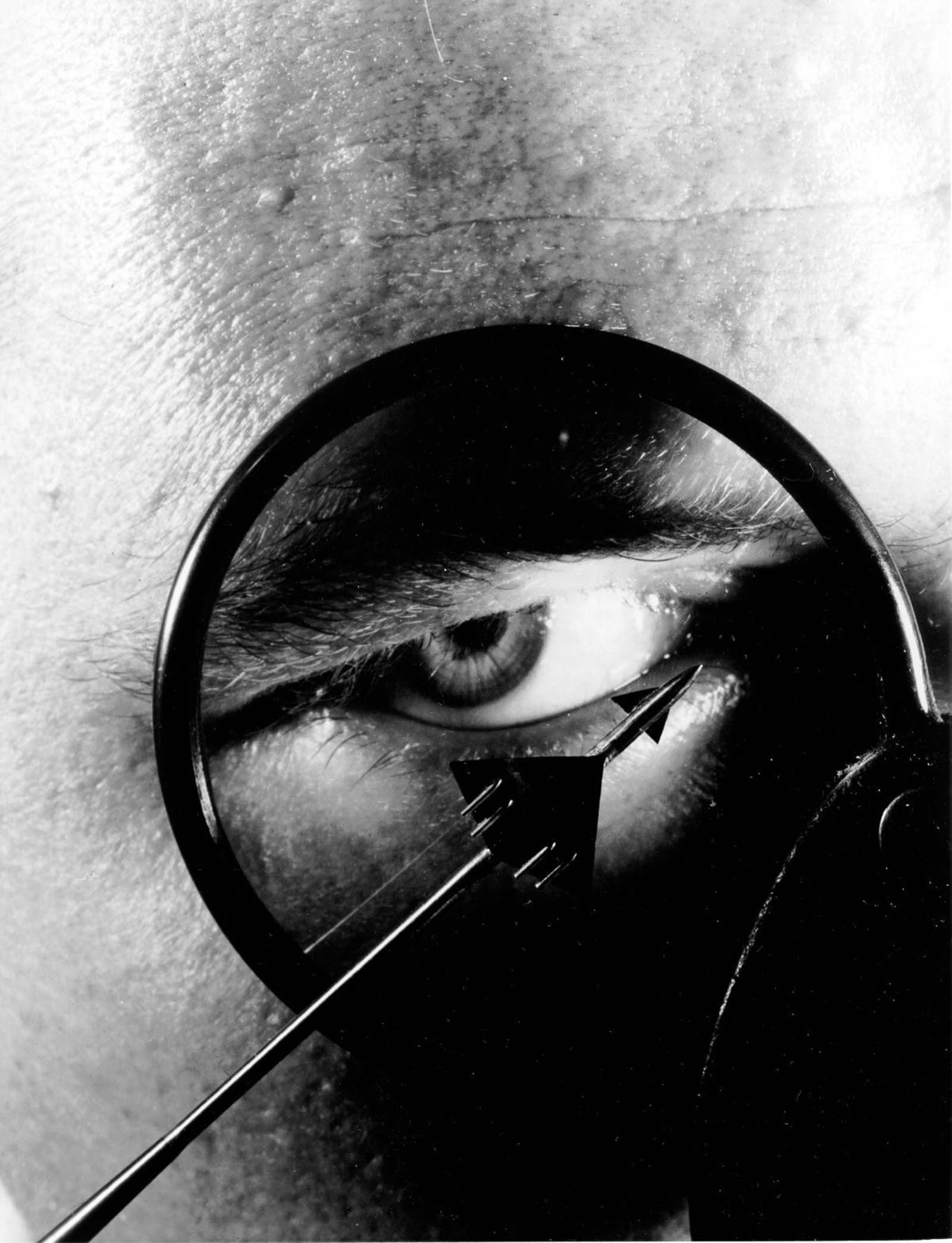
Returning from space presented a different kind of problem: the intense heat generated as a vehicle plows back into the atmosphere at thousands of miles per hour. Shadowgraph imaging — a technique that made shockwaves and pressure disturbances visible — revealed how a blunt-nosed vehicle could actually use its own shockwave as a heat shield, keeping the vehicle cooler during reentry than a sharp-nosed design would.

Shadowgraphs of fluid disturbances around high-velocity vehicles demonstrate how a blunt-bodied vehicle produces a shockwave in front of the vehicle, which allows it to stay cooler during reentry, 1960.
A 10-story bank of vanes which turn the air around one of the four corners of the 40 x 80-foot Wind Tunnel at Ames Research Center.

Sonic boom research was another pressing concern as supersonic aircraft moved from experimental to operational status. At Langley, a one-inch scale model of a supersonic aircraft design was suspended inside a four-foot supersonic tunnel, with pressure measurements taken up to 50 inches from the model — simulating conditions at altitudes up to 40,000 feet.

A one-inch scale model of a typical supersonic airplane design is examined before being installed for sonic boom studies in the four-foot supersonic tunnel at Langley Research Center.

Pressure measurements are made in the tunnel up to 50 inches away from the model, simulating altitudes up to 40,000 feet, 1960.

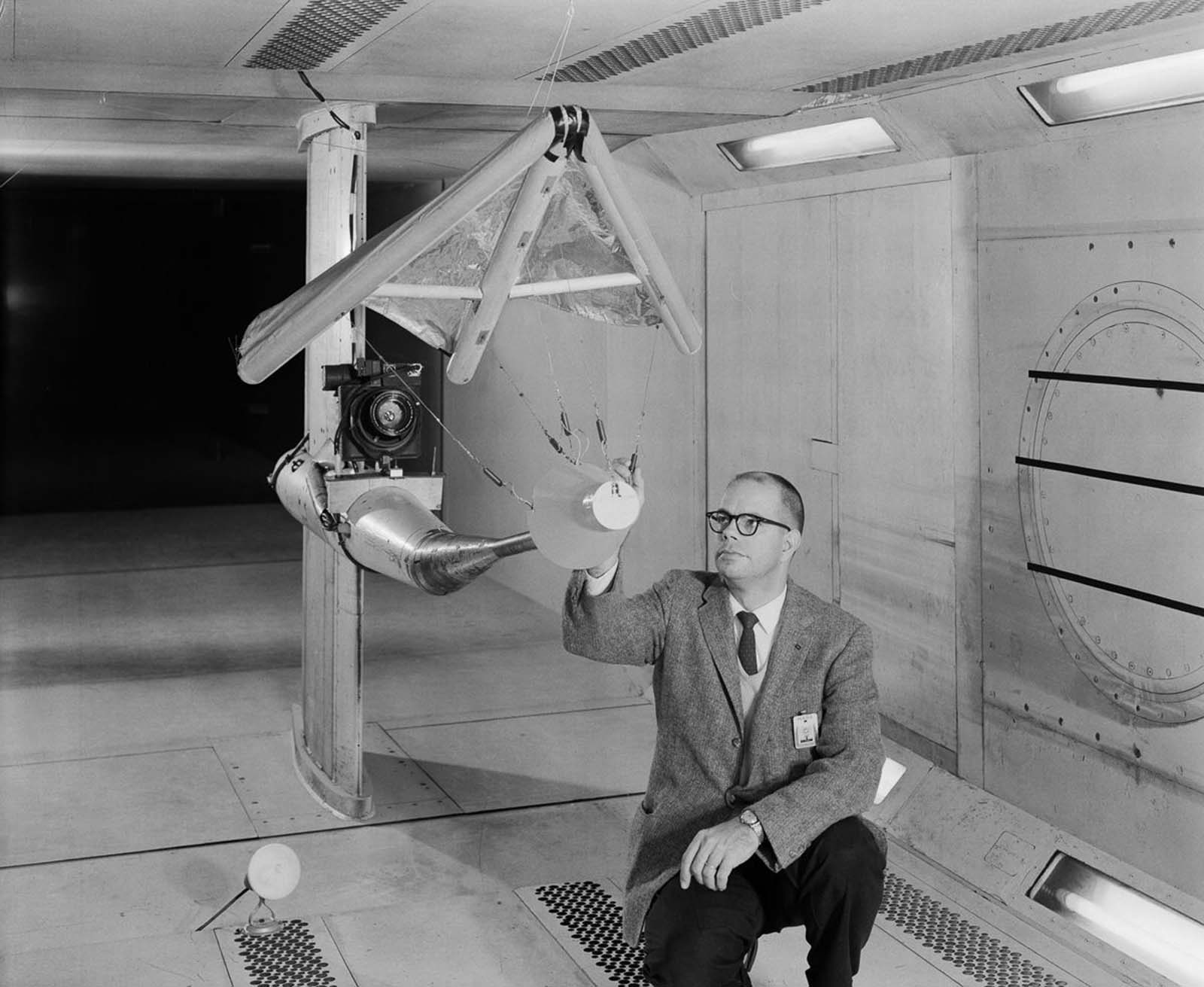
The Gemini program brought its own unusual tunnel subjects. A paraglider — officially called the Rogallo Wing — was proposed as a way to give Gemini capsules the ability to land precisely on solid ground rather than splashing down in the ocean. The concept was tested in a 300-mph, 7-by-10-foot wind tunnel, but the paraglider failed to deploy reliably enough for operational use and the program was canceled.

W. C. Sleeman, Jr. inspects a model of a paraglider in the 300 mph, 7 x 10-foot Wind Tunnel.

The paraglider, or

The Apollo program demanded testing of an entirely different order. Heat shield materials for the Apollo command module were evaluated in the 9-by-6-foot Thermal Structures Tunnel, where engineers subjected candidate materials to the thermal conditions of reentry before committing to any final design.

Technicians install a model of an Apollo command module in the 9 x 6-foot Thermal Structures Tunnel for tests of possible heat shield materials, 1962.

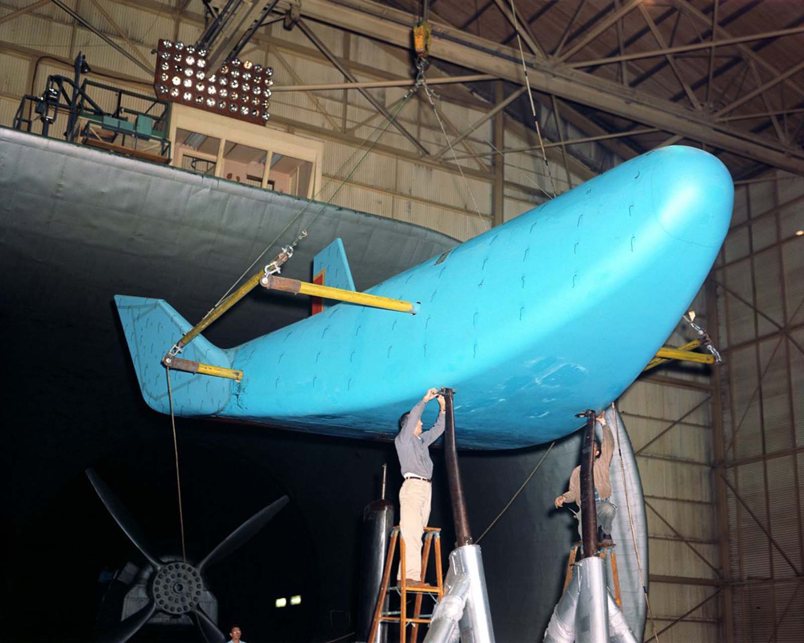
Lifting bodies — vehicles that generate lift from their fuselage shape rather than traditional wings — were another area of active research during the 1960s. The HL-10, one of NASA’s most successful lifting body designs, was tested at full scale in the 30-by-60-foot Full Scale Tunnel at Langley in 1964, helping engineers understand how the unusual shape would behave across a range of flight conditions.

A full scale model of the HL-10 lifting body mounted in the 30 x 60 Full Scale Tunnel at Langley, 1964.

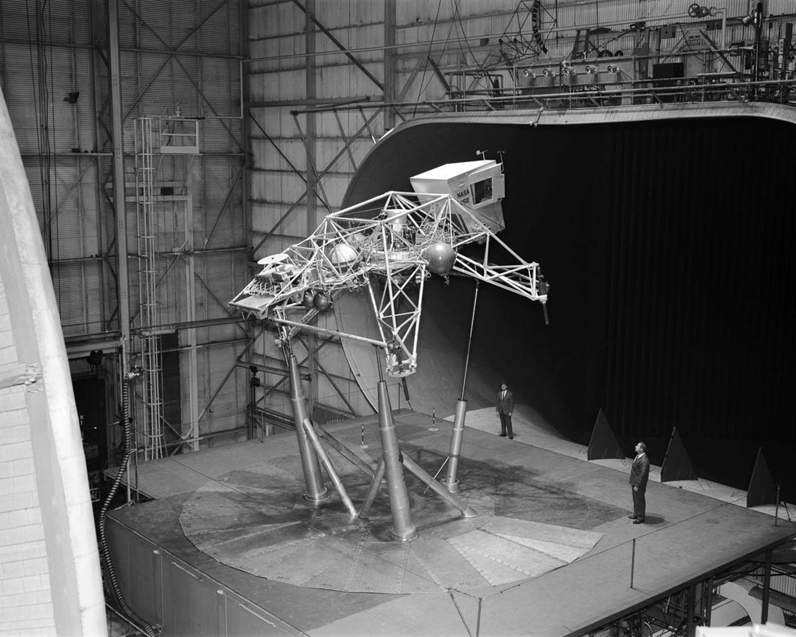
Training astronauts to land on the Moon required building machines that had never existed before. The Bell Lunar Landing Training Vehicle — a spindly, jet-powered contraption designed to mimic the handling of the lunar module — also passed through the Full Scale Tunnel so engineers could study its aerodynamic properties on Earth before any astronaut climbed aboard.

The Bell Lunar Landing Training Vehicle in the 30 x 60 Full Scale Tunnel.

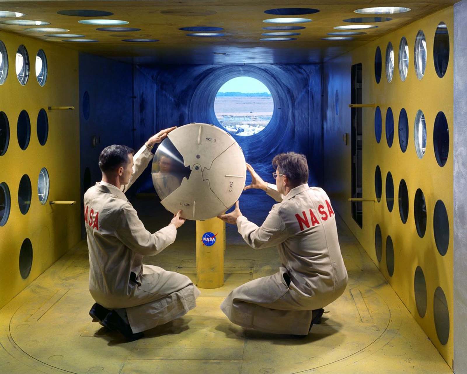
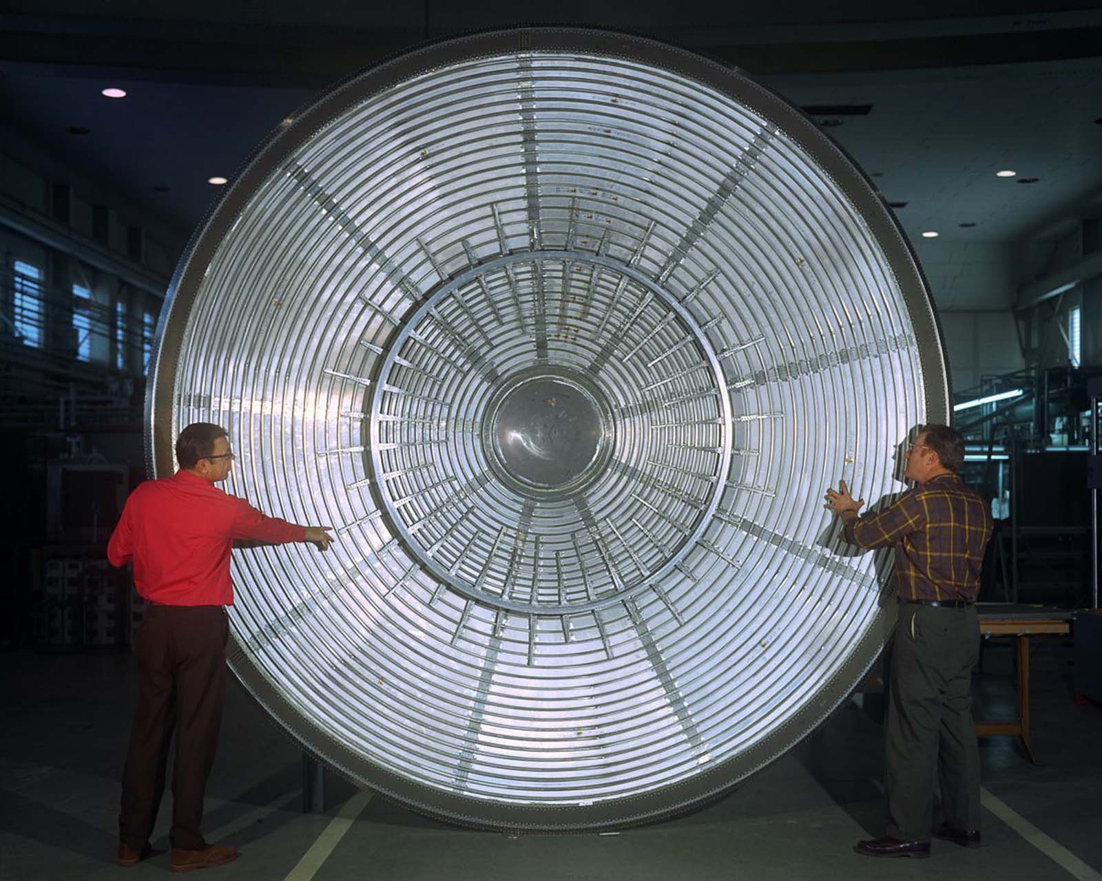
Wind tunnel work extended beyond Earth’s atmosphere in another sense — it helped prepare spacecraft for entry into the atmospheres of other planets. The aeroshell that protected the Viking lander during its plunge into the Martian atmosphere in 1976 was shaped and validated through extensive tunnel testing, ensuring it could handle the heating and pressure of a descent through an atmosphere very different from Earth’s.

The aeroshell which protected the Viking lander during its entry into the Martian atmosphere, 1973

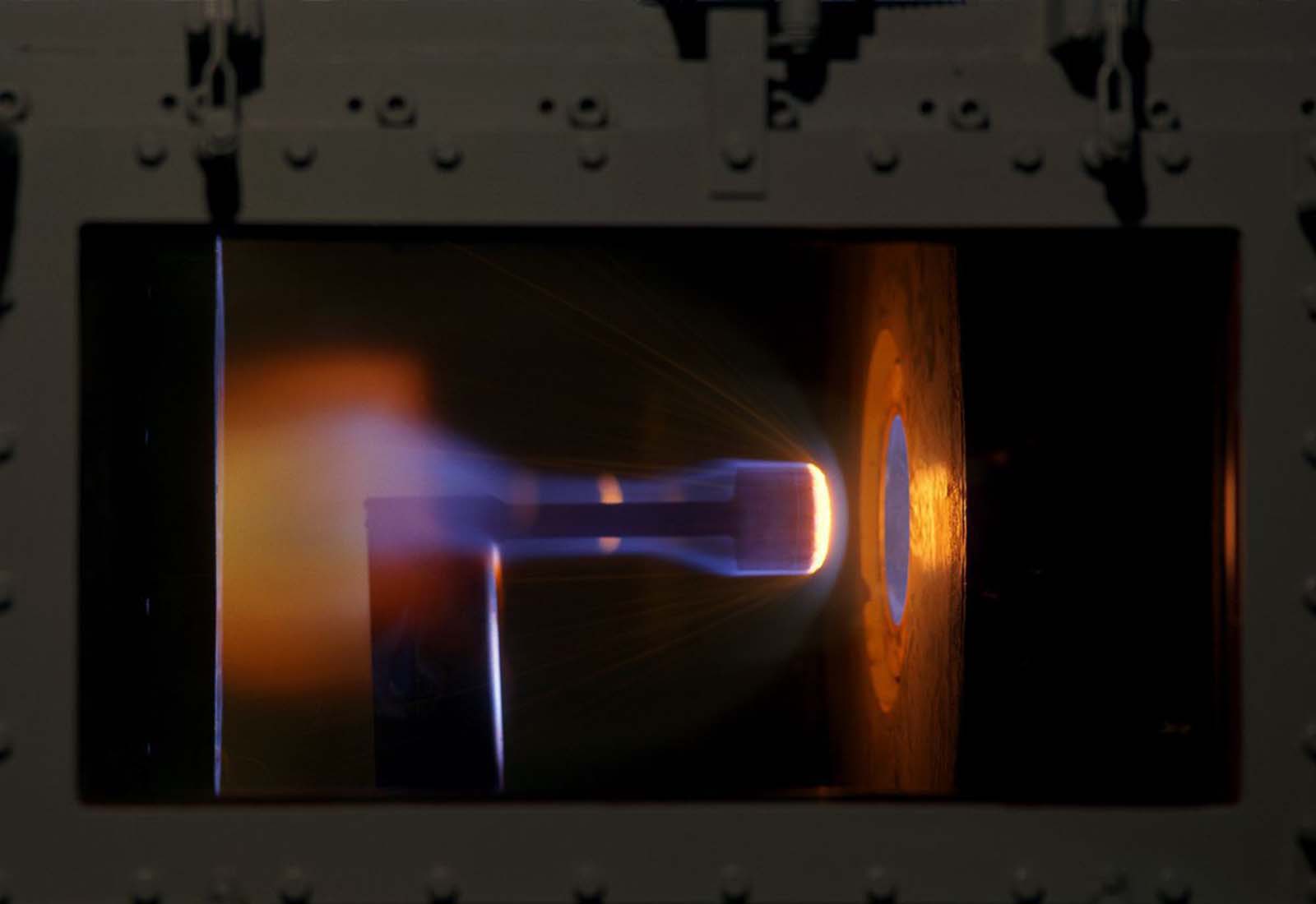
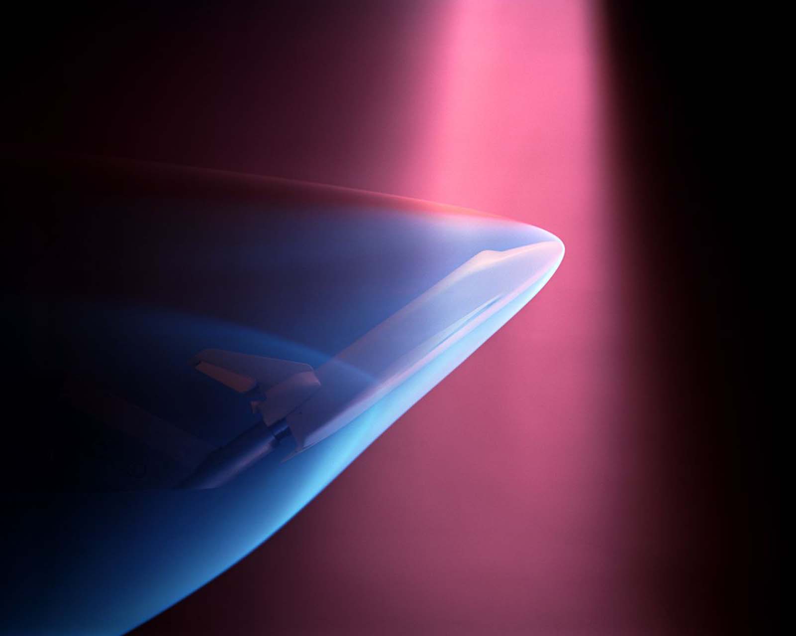
By the mid-1970s, the Space Shuttle program dominated NASA’s wind tunnel schedule. Thermal insulation materials for the shuttle’s exterior were tested at high temperatures, and scale models of the orbiter were placed inside tunnels that could recreate the ionized gas — plasma — that surrounds a returning shuttle as it re-enters the atmosphere at hypersonic speed.

Thermal insulation materials for the Space Shuttle are tested at high temperatures, 1975.
A space shuttle model undergoes a wind tunnel test simulating the ionized gasses that surround a shuttle as it reenters the atmosphere, 1975.

The shuttle’s design evolved through hundreds of tunnel runs. Engineers at Marshall Space Flight Center tested configurations that included proposed liquid booster modules — components that were ultimately not adopted in the shuttle’s final design, but which required thorough aerodynamic evaluation before being ruled out.

A Marshall Space Flight Center engineer holds a replica of the proposed Liquid Booster Module while observing the testing of a small Space Shuttle orbiter model at Wind Tunnel, 1980

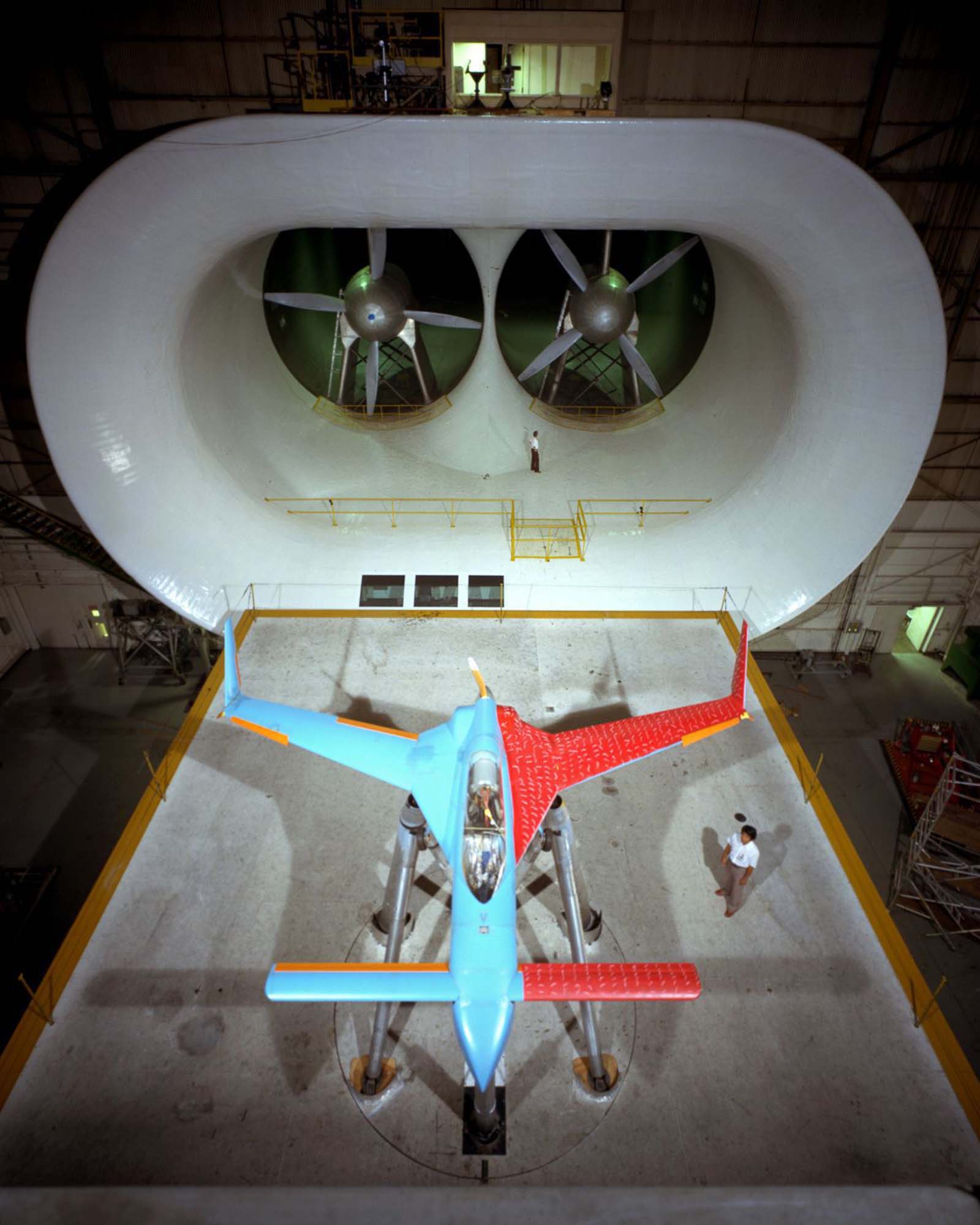
Not every tunnel subject was a government military project. In 1981, Langley researchers built and tested a replica of the Rutan Model 33 VariEze — a civilian composite aircraft designed by Burt Rutan — inside the 30-by-60-foot Full Scale Tunnel. The model was not built to fly on its own, but it was fitted with an electric motor to spin its propeller and generate realistic airflow conditions for the aerodynamics study.

The Rutan Model 33 VariEze was built by the Model and Composites Section of Langley Research Center and then tested in the 30 x 60 Full Scale Tunnel.

The craft was not built for flight, but did have an electric motor installed to drive the propeller as part of its aerodynamics study in the tunnel, 1981.

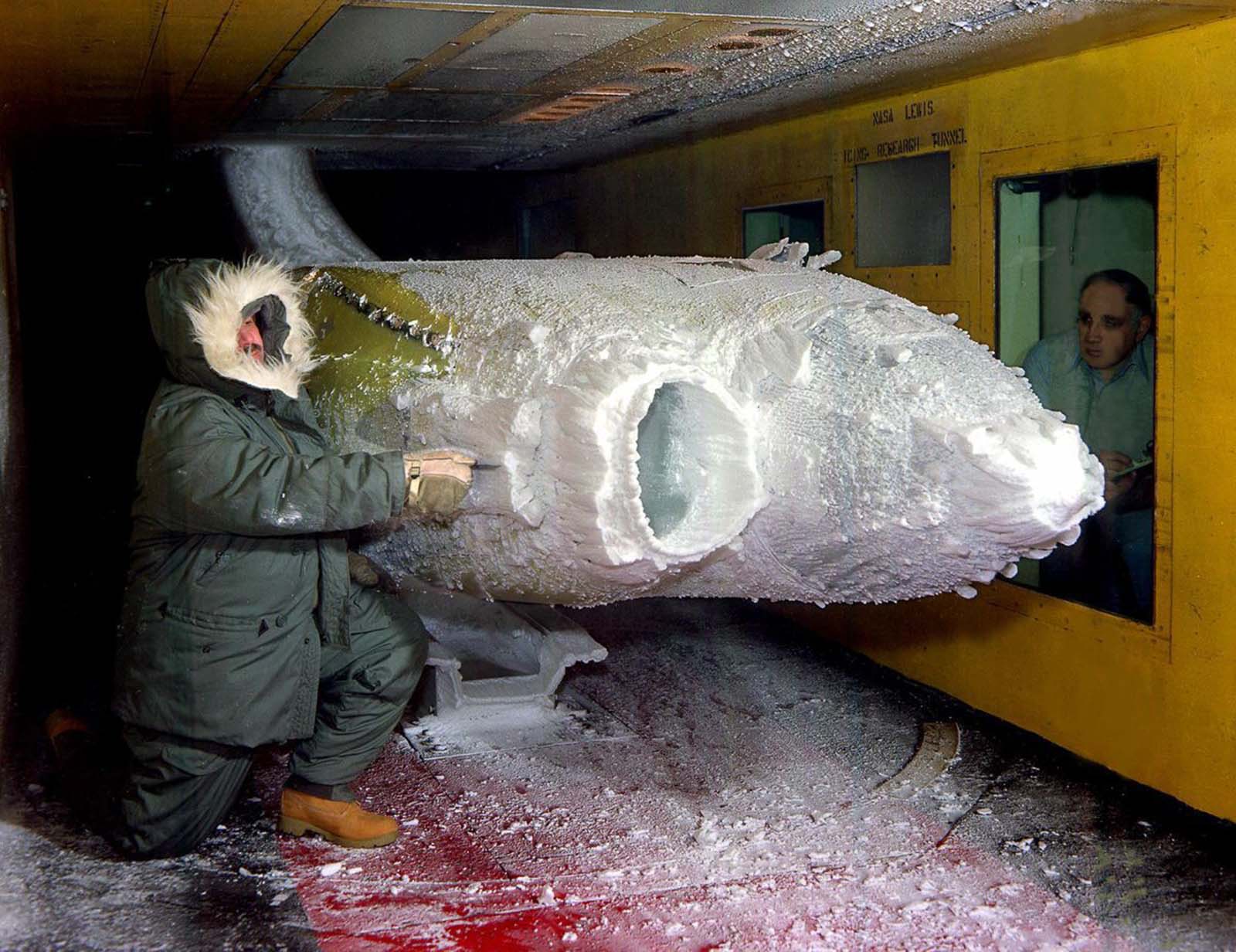
Specialized tunnels addressed problems that standard aerodynamic testing couldn’t cover. The Icing Research Tunnel allowed engineers to study how ice forms on aircraft components in the cold, moisture-laden air of the upper atmosphere — a critical safety concern for any aircraft flying in winter conditions or at high altitude.

A researcher examines the ice build-up on a turboprop engine nacelle in the Icing Research Tunnel, 1983.

The National Transonic Facility at Langley, opened in the 1980s, pushed wind tunnel capability into new territory. By using pressurized nitrogen gas instead of air, it could simulate the aerodynamic conditions experienced by large aircraft at transonic speeds — the range just below and just above the speed of sound — at a level of accuracy no previous tunnel had achieved.

NASA technician W.L. Jones inspects a transport model Pathfinder I between test runs at Langley's National Transonic Facility, 1986.
NASA technician W.L. Jones inspects a transport model Pathfinder I between test runs at Langley’s National Transonic Facility, 1986.

The Spin Tunnel at Langley continued to see regular use through the late 1980s, testing aircraft models to understand how they recover — or fail to recover — from a spin. The data from these tests directly informed the design of flight control systems and emergency recovery procedures.

A model aircraft is tested in the Spin Tunnel, 1987.

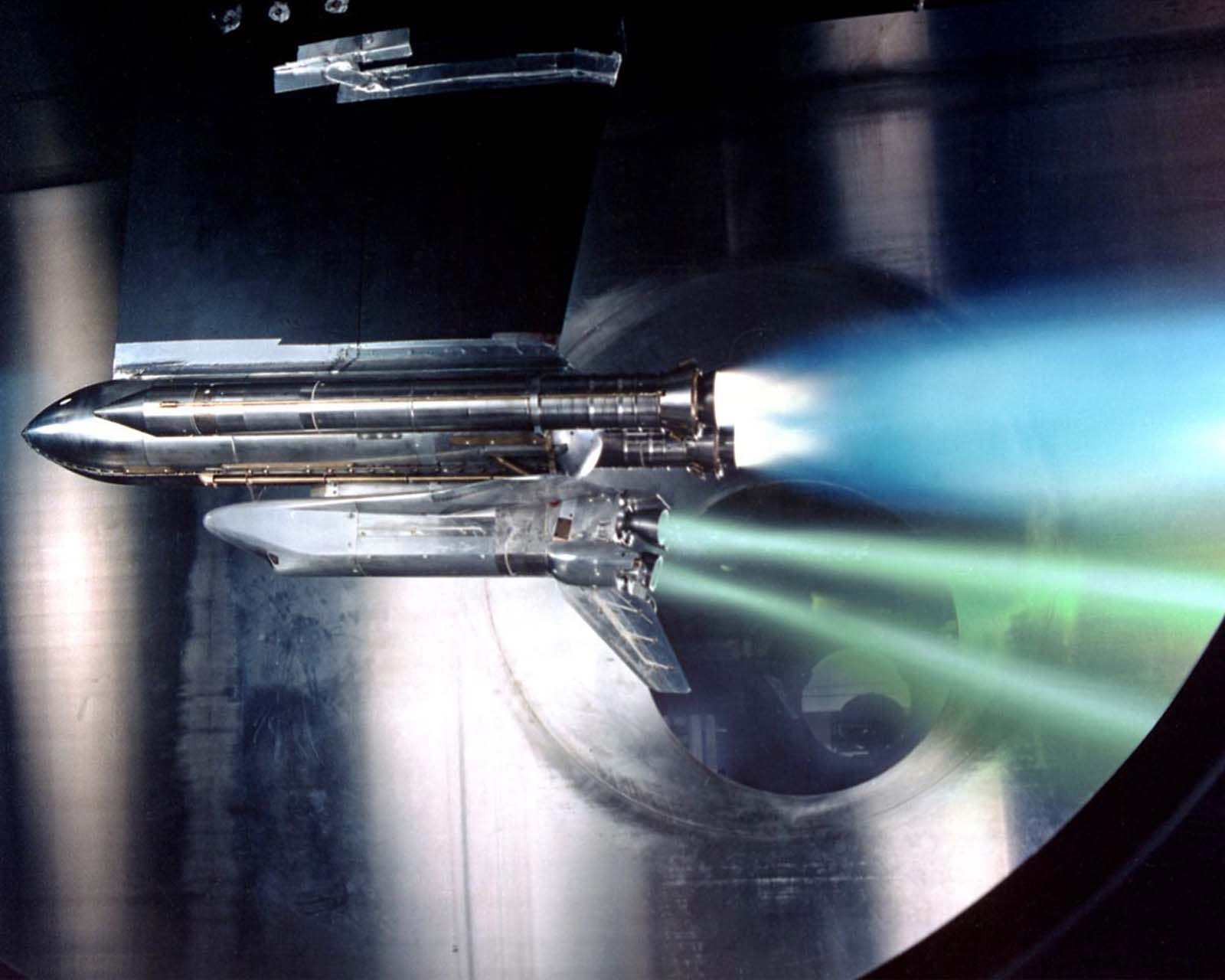
Propulsion systems also faced their own tunnel testing requirements. At the John H. Glenn Research Center in 1988, engineers conducted tests simulating a Space Shuttle main engine failure — studying the forces and flow dynamics involved so that emergency systems could be designed to handle the worst-case scenario.

A test of Space Shuttle main engine failure at the John H. Glenn Research Center, 1988.

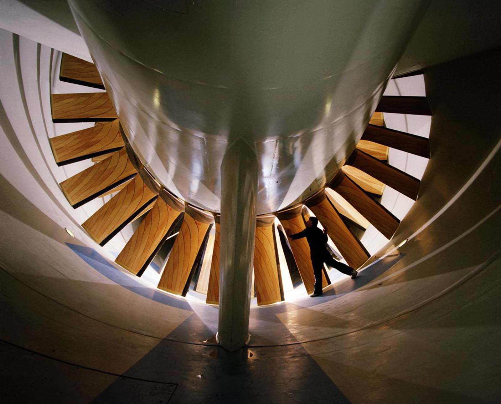
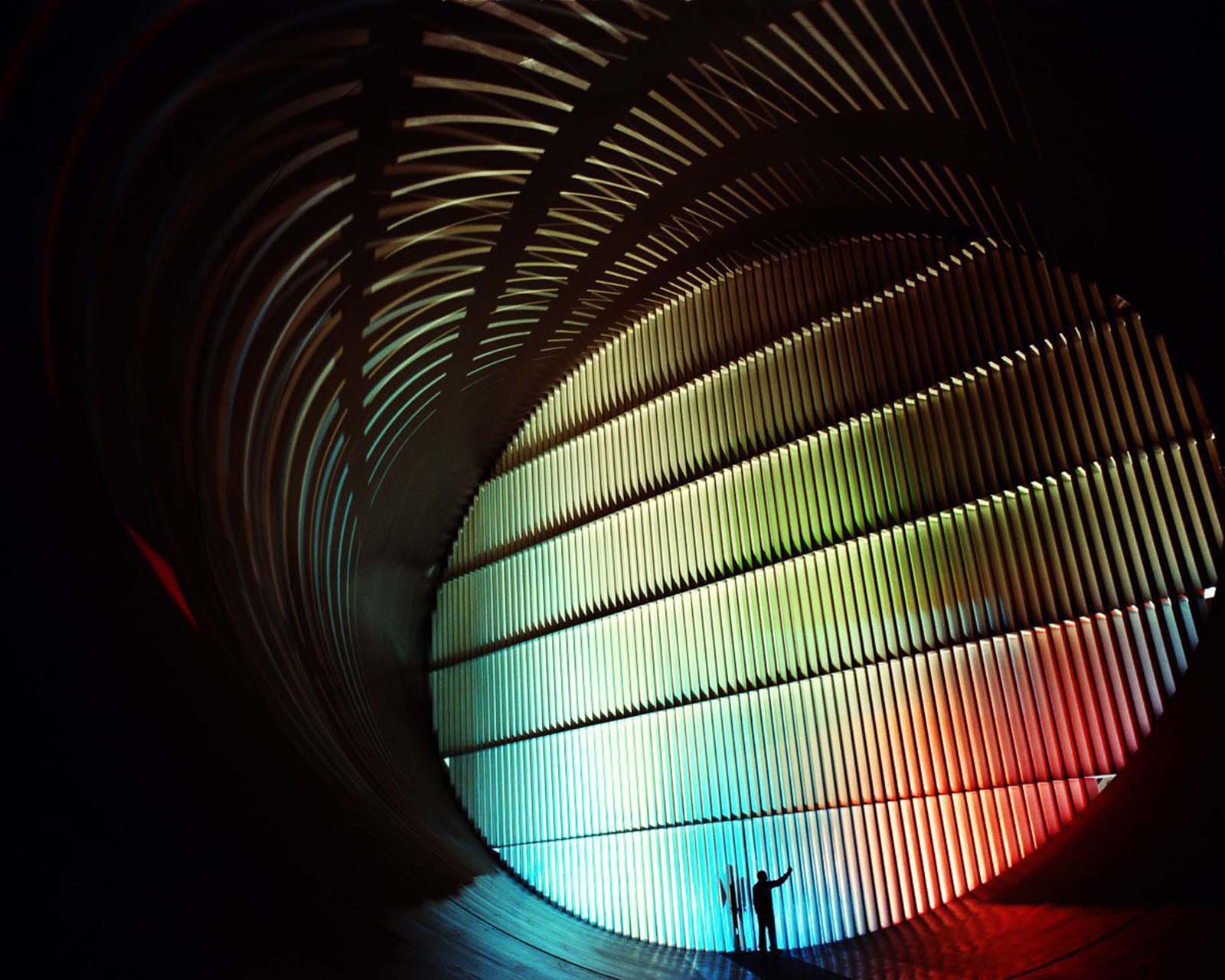
By 1990, Langley’s 16-Foot Transonic Tunnel was equipped with two 34-foot-diameter fans — a scale that reflects just how much raw power is required to drive a modern high-speed research tunnel. Around the same time, the tunnel’s turning vanes, which redirect airflow around the corners of the closed-loop circuit, stood as a reminder of the mechanical sophistication hidden inside these massive structures.

One of the two 34-foot-diameter fans in the 16-Foot Transonic Tunnel at Langley Research Center, 1990.
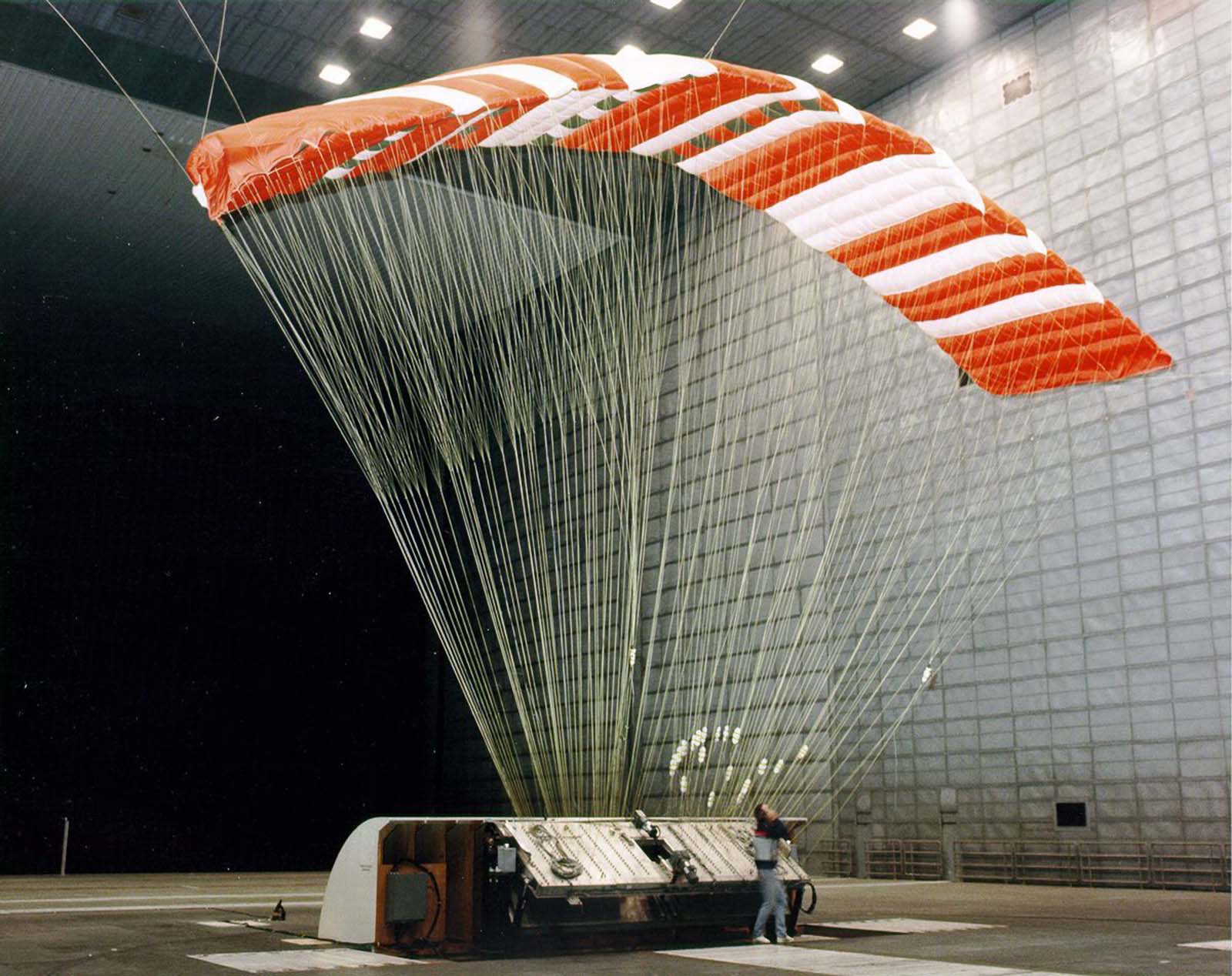
The Pioneer Aerospace Parafoil undergoes testing in the world's largest wind tunnel, the 80 x 120-Foot Tunnel at NASA's Ames Research Center in Mountain View, 1990
The Pioneer Aerospace Parafoil undergoes testing in the world’s largest wind tunnel, the 80 x 120-Foot Tunnel at NASA’s Ames Research Center in Mountain View, 1990
Turning vanes in the 16-Foot Tunnel at Langley, 1990.

The Ames Research Center’s 40-by-80-foot tunnel had been expanded into an 80-by-120-foot facility — the largest wind tunnel in the world — capable of testing full-size aircraft and large aerospace structures. That same year, a Pioneer Aerospace parafoil was tested inside it, demonstrating how the tunnel’s enormous test section could accommodate objects of almost any shape or size.

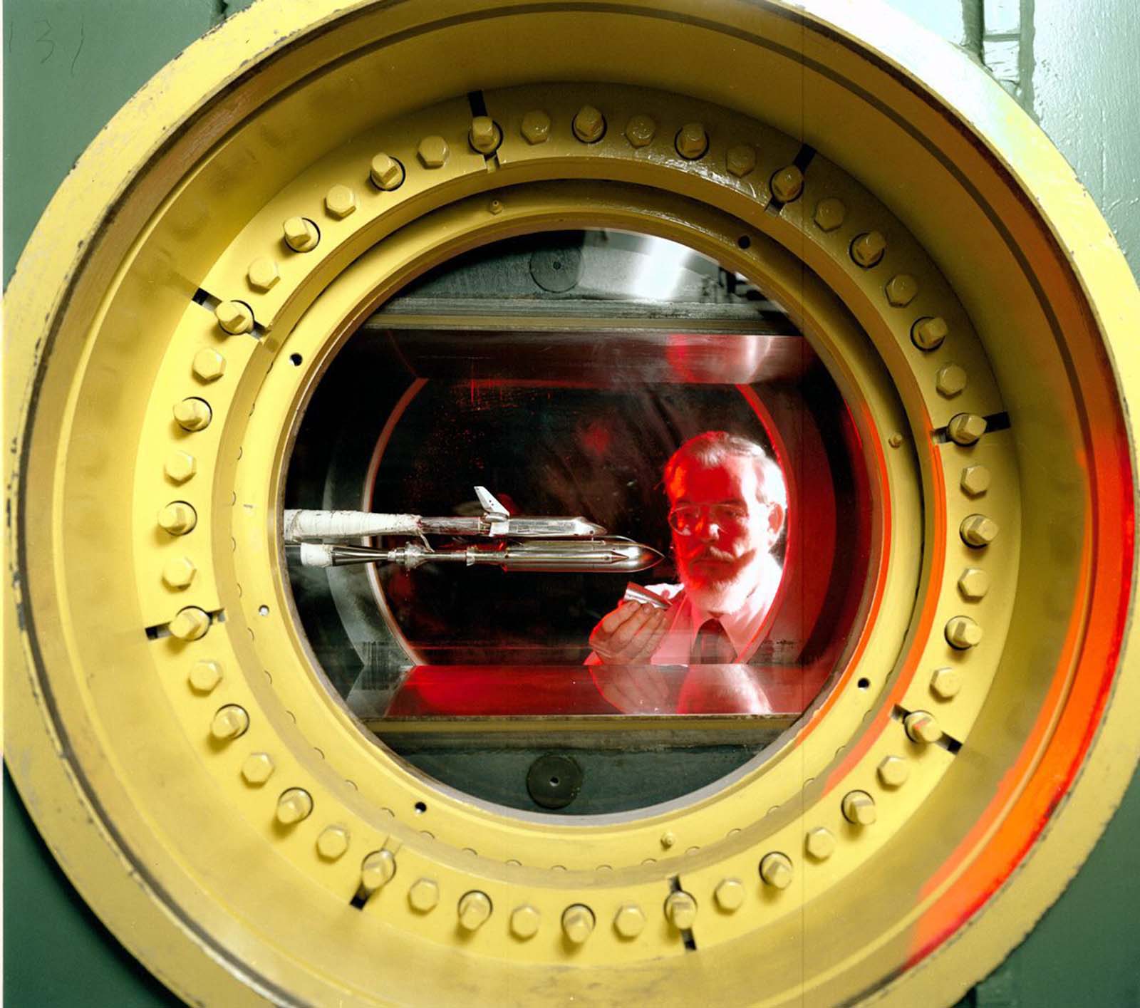
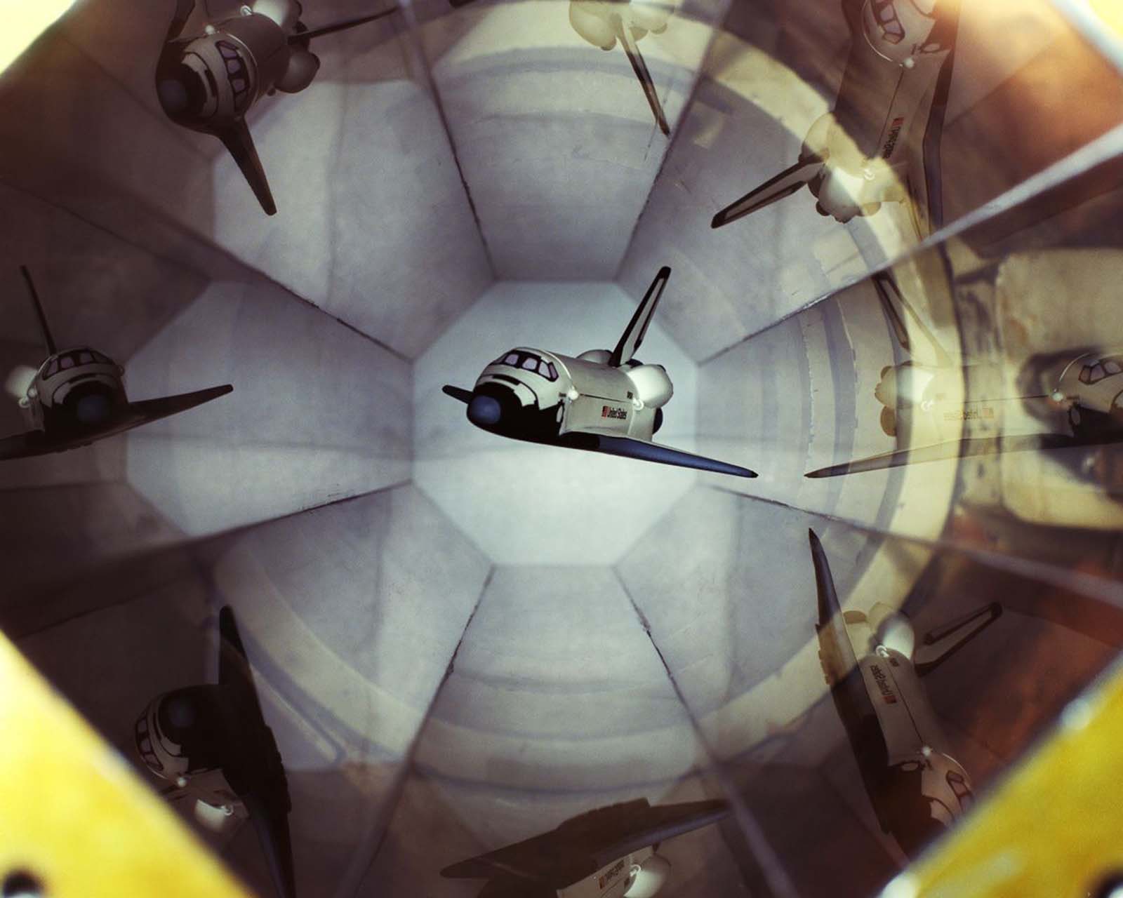
Some of the most technically advanced tunnel work happened at smaller scales. MIT and NASA Langley collaborated on a six-inch Magnetic Suspension and Balance System tunnel, in which a shuttle model was held stationary inside the test section using electromagnets alone — no physical supports that could distort the airflow. The tunnel itself was hand-crafted from mahogany and operated at up to Mach 0.5, requiring massive power supplies to run the electromagnets that held the model in position.

A shuttle model is magnetically suspended in the transparent hexagonal test section of the MIT/NASA Langley 6 inch MSBS.

Massive power supplies are required to drive electromagnets for model position control. The low speed (Mach 0.5) wind tunnel was handcrafted from mahogany, 1991.

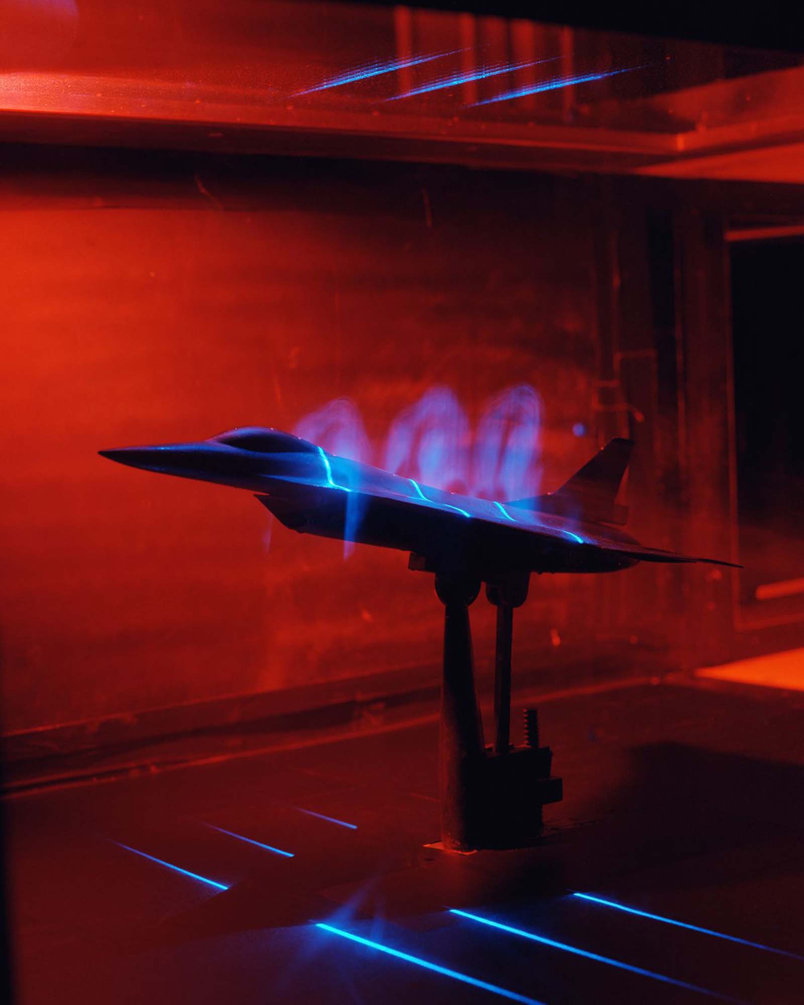
Flow visualization techniques advanced steadily alongside tunnel engineering. By 1992, engineers were using lasers to illuminate sheets of smoke inside the test section, making the airflow patterns around models like the F-16 fighter visible in precise, high-contrast detail. What had once been observed by eye with hand-injected smoke had become a sophisticated optical science.

An F-16 model in a flow visualization test using smoke and a laser light sheet to illuminate the smoke, 1992.
Enjoyed this post? Get new ones in your inbox.

Leave a Comment

Your email address will not be published. Required fields are marked *

Share this Post 🥺

Please take a moment to share this content. Your support is greatly appreciated! 🙌🙏

Share this Post 🥺

Please take a moment to share this content. Your support is greatly appreciated! 🙌🙏
Scroll to Top
 
Hey Friend, Before You Go.. Please like & follow for more interesting content